Steam heating corrugated roller of single face corrugation making machine

A technology for corrugating machines and corrugating rollers, applied in the field of corrugating rollers, can solve the problems of waste of rollers, troublesome installation or roller replacement, and inability to discharge condensed water, and achieve the effect of high heat transfer efficiency

Inactive Publication Date: 2008-11-05
HUBEI JINGSHAN LIGHT INDAL MACHINERY
View PDF0 Cites 7 Cited by
  • Summary
  • Abstract
  • Description
  • Claims
  • Application Information

AI Technical Summary

Problems solved by technology

A lot of waste is caused by the deformation of the roller in the production process
[0003] Traditional corrugated rolls generally use a two-way rotary joint to feed steam into the inner cavity of the roll, transfer the heat energy of the saturated steam to the surface of the roll, and form condensed water after heat transfer. Siphon 7 tube drainage structure, there must always be a certain minimum gap between the siphon tube 7 and the inner wall of the roller
In addition, the roller has a certain width, and a certain amount of condensed water 8 will always accumulate at the bottom of the inner cavity of the roller, and the condensed water 8 below the mouth of the siphon cannot be discharged.
The siphon tube 7 is used for drainage, and the gap between the siphon port and the inner wall of the roller needs to be adjusted accurately, and it is troublesome to install or change the roller each time

Method used


Image

  • Steam heating corrugated roller of single face corrugation making machine
  • Steam heating corrugated roller of single face corrugation making machine
  • Steam heating corrugated roller of single face corrugation making machine

Examples


Embodiment Construction

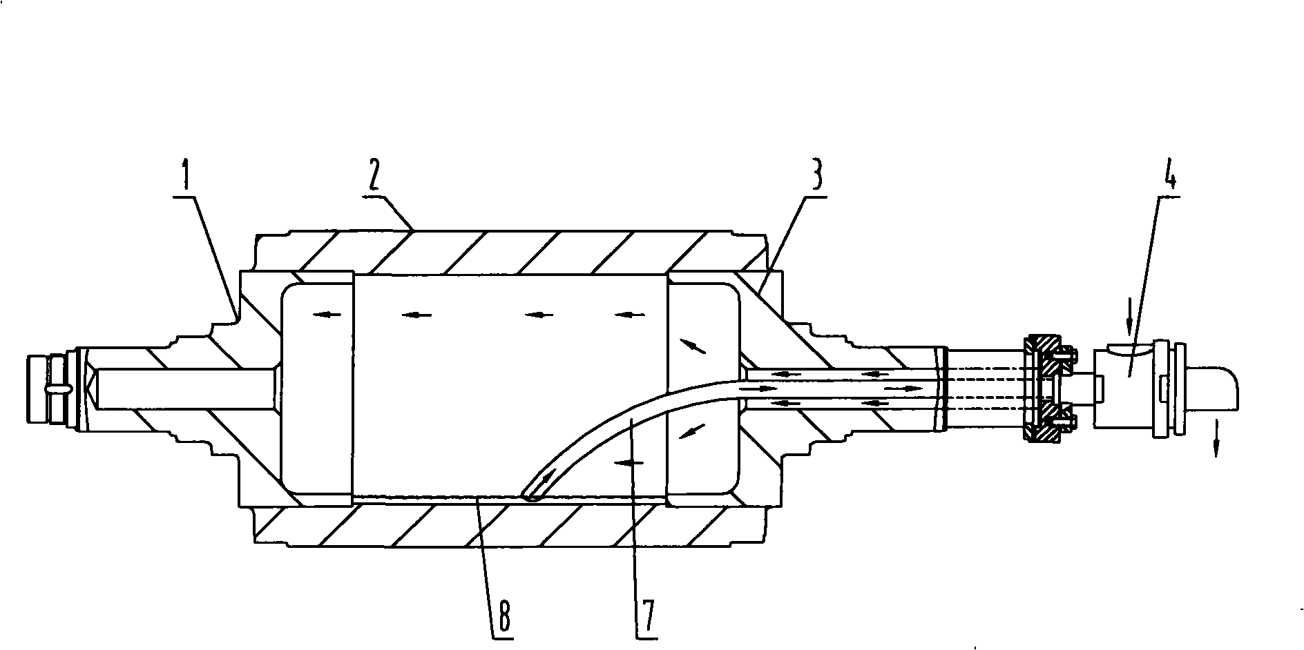
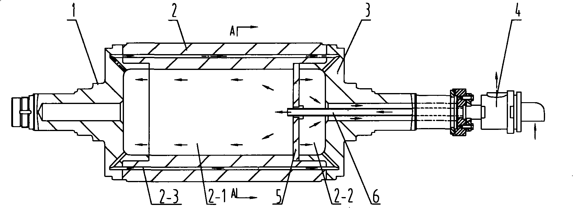
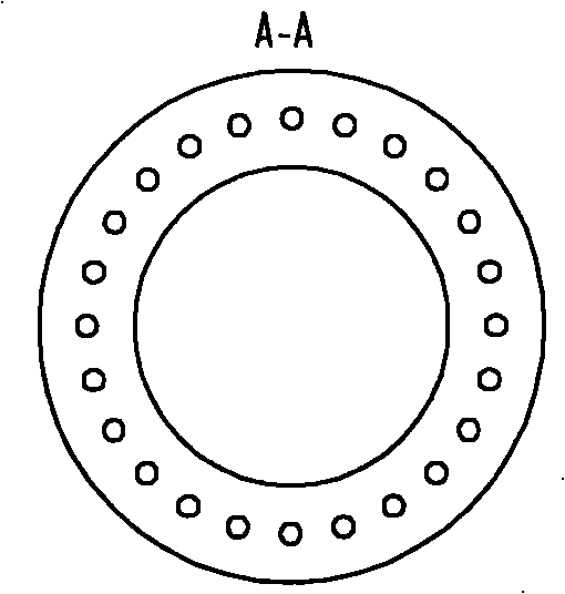
[0008] In the original corrugated roll (see figure 1 ) directly on the surface, remove the siphon, and uniformly process a week of heat conduction holes around the roller (see figure 2 ), the steam chamber and the condensation chamber are divided into a steam chamber and a condensation chamber in the cylinder through a partition. The steam chamber is 8-10 times larger than the condensation chamber. The chamber communicates with the condensed water outlet in the right half shaft, the inlet end of the steam circulation heat conduction hole communicates with the steam chamber, and the outlet end communicates with the condensation chamber (see image 3 ).

[0009] Working mode: The saturated steam is introduced into the steam chamber through the steam pipe, and the steam in the steam chamber enters the heat conduction hole to heat the roller. In this way, the steam cavity and the heat conduction holes are fed with steam, which increases the heat exchange area, rapidly heats the...


PUM


Abstract

The invention provides a single-surface corrugating machine steam heating corrugating roller, comprising a corrugating roller, a baffle (5) and a steam pipe (6); a cylinder body (2) is internally divided into a steam chamber (2-1) and a condensing chamber (2-2) by the baffle (5); one end of the steam pipe (6) is communicated with a steam inlet passage which is arranged in a right half shaft (3) and the other end is communicated with the steam chamber (2-1); the condensing chamber (2-2) is communicated with a condensed water outlet passage which is arranged in the right half shaft (3); the circumferential of the wall of the cylinder body (2) is uniformly provided with steam circulation heat conducting holes (2-3). The single-surface corrugating machine steam heating corrugating roller has the advantages that condensed water can not be gathered in a heat conducting hole; the bent deformation of the roller can not be generated due to the temperature difference even when a roller is not rotated, and paper rotting phenomenon and base paper waste can not occur. Meanwhile, siphon pipes are not required, thus installation is convenient and malfunction is reduced.

Description

technical field [0001] The invention relates to a corrugating roller on a single-sided corrugating machine in corrugating machines. Background technique [0002] The corrugating roller is a very important part on the single face corrugating machine. The corrugated base paper is heated by a pair of upper and lower corrugating rollers, rolled into a corrugated corrugated paper, and then compounded into a single-sided corrugated board after being glued. When the corrugated base paper is formed, it must be preheated to evaporate the excess water in the base paper, and at the same time adjust the water content of the base paper in the entire width direction, and ensure the temperature required for the base paper to be formed. Otherwise, the base paper cannot be formed or the corrugated cardboard after forming cannot meet the requirements; therefore, it is very important to ensure the uniform temperature of the surface of the corrugating roller for the forming of the base paper. ...

Claims


Application Information

Patent Timeline
Patent Type & Authority Applications(China)
IPC IPC(8): B31F1/20
Inventor 杨皓邹汉生范德金周剑波刘辉黄艮兵
Owner HUBEI JINGSHAN LIGHT INDAL MACHINERY
Why Eureka
Try Eureka