Mould for making glass container

A glass container and mold technology, applied in the field of making glass container molds, can solve the problems of inconsistency, uneven distribution of material and liquid, and inability to guarantee the overall quality of the bottle, and achieve the effect of ensuring consistent wall thickness and uniform distribution of materials

Active Publication Date: 2008-11-05
CHANGSHU WEIHENG MOLD MFG
View PDF0 Cites 60 Cited by
  • Summary
  • Abstract
  • Description
  • Claims
  • Application Information

AI Technical Summary

Problems solved by technology

[0002] Glass containers have a wide range of uses, and processing various glass containers requires the use of corresponding molds. Take the necked beer bottles, beverage bottles or other similar bottles that are seen in daily life as examples. During the process, due to the low temperature of the neck glass, it is very easy to cause uneven distribution of the material liquid, which will affect the wall thickness of the bottle neck and make the overall quality of the bottle unable to be guaranteed.

Method used


Image

  • Mould for making glass container

Examples


Embodiment 1

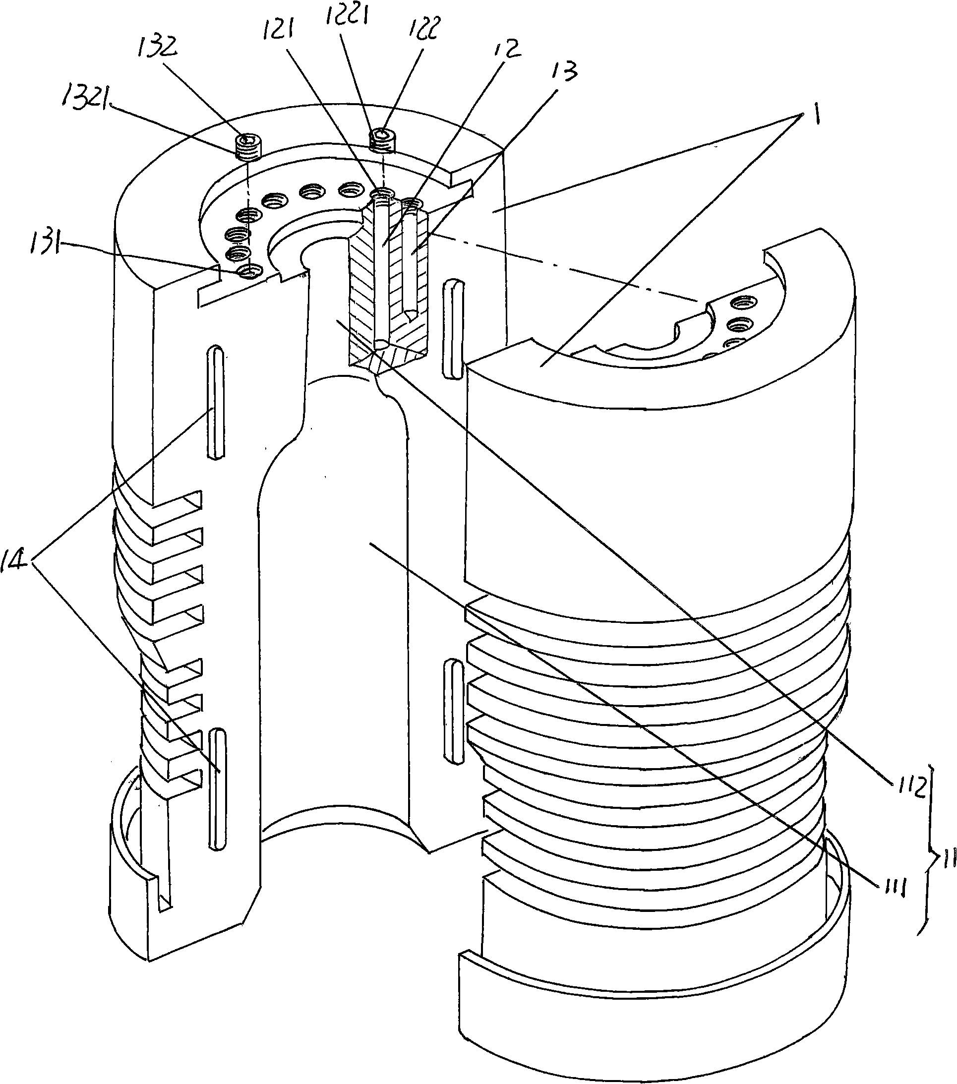
[0016] Please refer to the attached drawing, which shows a pair of bottle half-molds 1 opposite to each other with the same shape and structure for making beer bottles, and a bottle mold for forming beer bottles is processed at the center of the inner wall of each bottle half-mold 1 Cavity 11, the bottle mold cavity 11 includes a lower bottle body cavity 111 and an upper bottle neck cavity 112, wherein the height of the bottle neck cavity 112 is 60 mm. On the top of a pair of bottle half-moulds 1 and around the bottle neck cavity 112, first and second heat preservation holes 12, 13 are provided at intervals. The distance between the hole 12 and the adjacent second heat-retaining hole 13 is 6 mm, which refers to the distance from the center of the first heat-retaining hole 12 to the center of the second heat-retaining hole 13 . The first heat preservation hole 12 has a depth of 60mm and a diameter of 6mm, and the second heat preservation hole 13 has a diameter of 6mm and a dept...

Embodiment 2

[0019] The figure is omitted, only the spacing between the first heat preservation hole 12 and the adjacent second heat preservation hole 13 is changed to 7mm, the diameter of the first and second heat preservation holes 12, 13 is changed to 5mm, and the depth of the first heat preservation hole 12 is Change it to 65mm, change the depth of the second heat preservation hole 13 to 55mm, change the height of the bottle neck cavity 112 of the bottle mold cavity 11 to 65mm, change the tenon protrusion 14 to a cylinder or cylindrical pin, and change the tenon protrusion cavity to a circular hole , and all the other are the same as the description to embodiment 1.

Embodiment 3

[0021] The figure is omitted, only the spacing between the first heat preservation hole 12 and the adjacent second heat preservation hole 13 is changed to 8mm, the diameters of the first and second heat preservation holes 12 and 13 are changed into 4.5mm, and the diameter of the first heat preservation hole 12 is changed into 4.5mm. The depth is changed to 55mm, the depth of the second heat preservation hole 13 is changed to 45mm, and the height of the neck cavity 112 of the bottle mold cavity 11 is changed to 55mm, all the other are the same as the description of embodiment 1.


PUM


Abstract

The invention provides a mold for producing a glass container and belongs to the technical field of mold. The mold includes a pair of half bottle molds that are opposite to each other, and a bottle die cavity is formed in the inner wall of each half bottle mold and is composed of a bottle body cavity and a bottleneck cavity. The mold is characterized in that a first heat-insulating hole and a second heat-insulating hole are alternatively distributed around the bottleneck cavity at the upper part of the half bottle mold, wherein, the depth of the two heat-insulating holes is different. The mold has the advantages that the temperature around the bottleneck cavity can be improved as the first heat-insulating hole and the second heat-insulating hole are arranged at the upper part of the half bottle mold and are corresponding to the surrounding of the bottleneck cavity, which is helpful to lead the materials to distribute evenly during the two blowing process and can guarantee that the wall thickness of the bottleneck is uniform.

Description

technical field [0001] The invention belongs to the technical field of moulds, in particular to a mold for making glass containers. Background technique [0002] Glass containers have a wide range of uses, and processing various glass containers requires the use of corresponding molds. Take the necked beer bottles, beverage bottles or other similar bottles that are seen in daily life as examples. During the process, due to the low temperature of the neck glass, it is very easy to cause uneven distribution of the feed liquid, thereby affecting the uneven wall thickness of the bottle neck, so that the overall quality of the bottle cannot be guaranteed. Contents of the invention [0003] The task of the present invention is to provide a mold for making glass containers that is conducive to the uniform distribution of material and liquid so as to ensure that the wall thickness of the neck of the bottle is consistent. [0004] The task of the present invention is accomplished ...

Claims


Application Information

Patent Timeline
Patent Type & Authority Applications(China)
IPC IPC(8): C03B9/24
Inventor 陆卫平
Owner CHANGSHU WEIHENG MOLD MFG
Why Eureka
Try Eureka