Structural crack bionic monitoring system and monitoring method thereof
A monitoring system and bionic technology, applied in the online monitoring system and its monitoring field, can solve the problems of unpredictable time and location, uneconomical, practical, long-term, online, accurate monitoring of cracks, and difficulty in clearly pointing out the specific location of damage, etc. , to achieve the effect of convenient and simple use, reliable results and high efficiency
- Summary
- Abstract
- Description
- Claims
- Application Information
AI Technical Summary
Problems solved by technology
Method used
Image
Examples
Embodiment 1
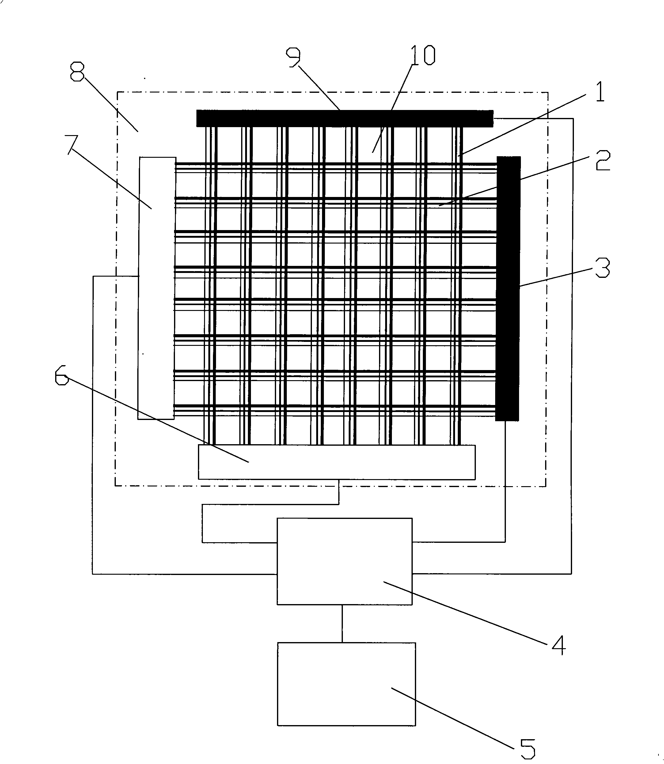
[0030] figure 1 It is a structural schematic diagram of Embodiment 1 of the present invention, as shown in the figure: the structural crack bionic monitoring system of the present invention is composed of multiple parallel smart lines I1 and multiple parallel smart lines II2 pasted on the surface of the concrete structure 8 to be monitored The monitoring unit of the smart line I1 and the smart line II2 are composed of three wires with different diameters and parallel to each other, which can monitor the cracks of the three different widths concerned. Conductors produce different tensile forces, and conductors of different diameters can withstand different breaking forces. According to the fracture conditions of conductors of different diameters, the width of cracks can be monitored; smart line I1 and smart line II2 are vertically intersected, and the adjacent smart line I1 The distance between the space and the adjacent smart line II2 is 10cm. According to the concrete structu...
Embodiment 2
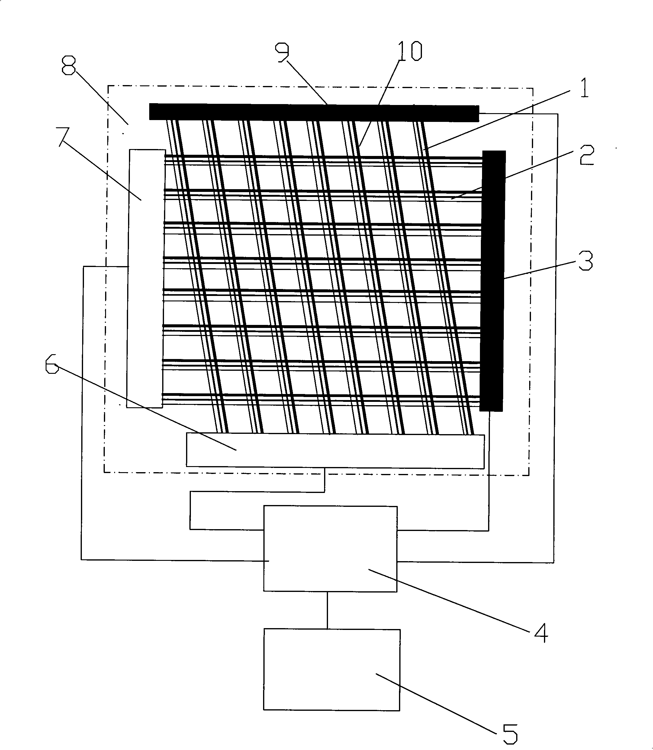
[0033] figure 2It is a structural schematic diagram of Embodiment 2 of the present invention, as shown in the figure: the structural crack bionic monitoring system of the present invention is composed of multiple parallel smart lines I1 and multiple parallel smart lines II2 pasted on the surface of the concrete structure 8 to be monitored The monitoring unit of the smart line I1 and the smart line II2 are composed of three wires with different diameters and parallel to each other, which can monitor the cracks of the three different widths concerned. Conductors produce different tensile forces, and conductors with different diameters can withstand different breaking forces. According to the fracture conditions of conductors with different diameters, the width of cracks can be monitored; the smart line I1 and smart line II2 are set at an inclined cross, and the inclined setting can adapt to the cracks that are prone to cracks. Horizontal or longitudinal cracks, but the vertical...
Embodiment 3
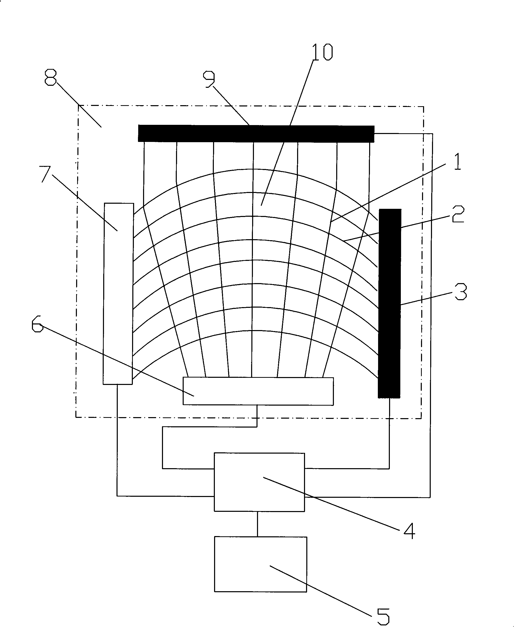
[0036] image 3 It is a structural schematic diagram of Embodiment 3 of the present invention, as shown in the figure: the structural crack bionic monitoring system of the present invention is composed of multiple parallel sensitive lines I1 and multiple parallel sensitive lines II2 pasted on the surface of the concrete structure 8 to be monitored The monitoring unit of the smart line I1 and the smart line II2 are composed of three wires with different diameters and parallel to each other, which can monitor the cracks of the three different widths concerned. Conductors produce different pulling forces, and conductors of different diameters can withstand different breaking forces. According to the fracture conditions of conductors of different diameters, the width of cracks can be monitored; smart line I1 and smart line II2 are set crosswise, and multiple smart lines I1 It is set in a fan-shaped divergence, and multiple smart lines II2 are set in parallel in a circular arc in t...
PUM
 Abstract
Description
Claims
Application Information
 - R&D
- Intellectual Property
- Life Sciences
- Materials
- Tech Scout
- Unparalleled Data Quality
- Higher Quality Content
- 60% Fewer Hallucinations
Browse by: Latest US Patents, China's latest patents, Technical Efficacy Thesaurus, Application Domain, Technology Topic, Popular Technical Reports.
© 2025 PatSnap. All rights reserved.Legal|Privacy policy|Modern Slavery Act Transparency Statement|Sitemap|About US| Contact US: help@patsnap.com


