Method for preparing multi-sheet printed circuit board

A technology for printed circuit boards and manufacturing methods, applied in the directions of printed circuit manufacturing, printed circuits, and assembling printed circuits with electrical components, can solve the problems of inability to use, reduce value, production time and labor costs, and simplify replacement. procedures, the effect of improving production efficiency

Inactive Publication Date: 2008-11-05
E TEEN +1
View PDF0 Cites 3 Cited by
  • Summary
  • Abstract
  • Description
  • Claims
  • Application Information

AI Technical Summary

Problems solved by technology

However, since the respective alignment marks on the upper and lower surfaces are not completely consistent on the horizontal projection plane, an offset error will be caused when the qualified single-piece printed circuit board for replacement is mounted on the multi-piece printed circuit board to be repaired, For example, when the unqualified single-piece printed circuit board 131 is cut and taken off according to the alignment marks 15 on the upper surface 11 with a characteristic pitch d1, and the qualified single-piece printed circuit board 23 is placed on the multi-section of its mother chip. On the one-piece printed circuit board 20, the operation of cutting and removing is carried out according to the alignment mark 26 on the other surface (ie, the lower surface 22) with the same feature distance d1, then when the qualified single-piece printed circuit board 232 is placed on the When the multi-piece printed circuit board 10 to be replaced, the distance between it and the adjacent point of the alignment mark 15 will be d1', which is different from the original distance d1", which is to generate an offset error.
This offset error will cause the replaced multi-piece printed circuit board 10 to produce too large error in the subsequent wiring process and cannot be used.
[0008] At present, the existing solution in the industry is to reserve more gaps on the joint surface when taking off the qualified single-chip printed circuit board 232, that is, the joint protrusion of the qualified single-chip printed circuit board 232 is relatively small. The joint recesses on the replacement multi-piece printed circuit board 10 are small, and the technicians use high-precision optical calibration instruments to compare and position during the installation process. However, this procedure will inevitably result in production time and manpower. A large amount of expenditure, and the replacement quality is not easy to control, thus reducing the value of this operation in the industry

Method used


Image

  • Method for preparing multi-sheet printed circuit board
  • Method for preparing multi-sheet printed circuit board
  • Method for preparing multi-sheet printed circuit board

Examples


Embodiment Construction

[0078] The following combination Figure 4 ~Fig. 9, describe the preferred embodiment of the present invention in detail:

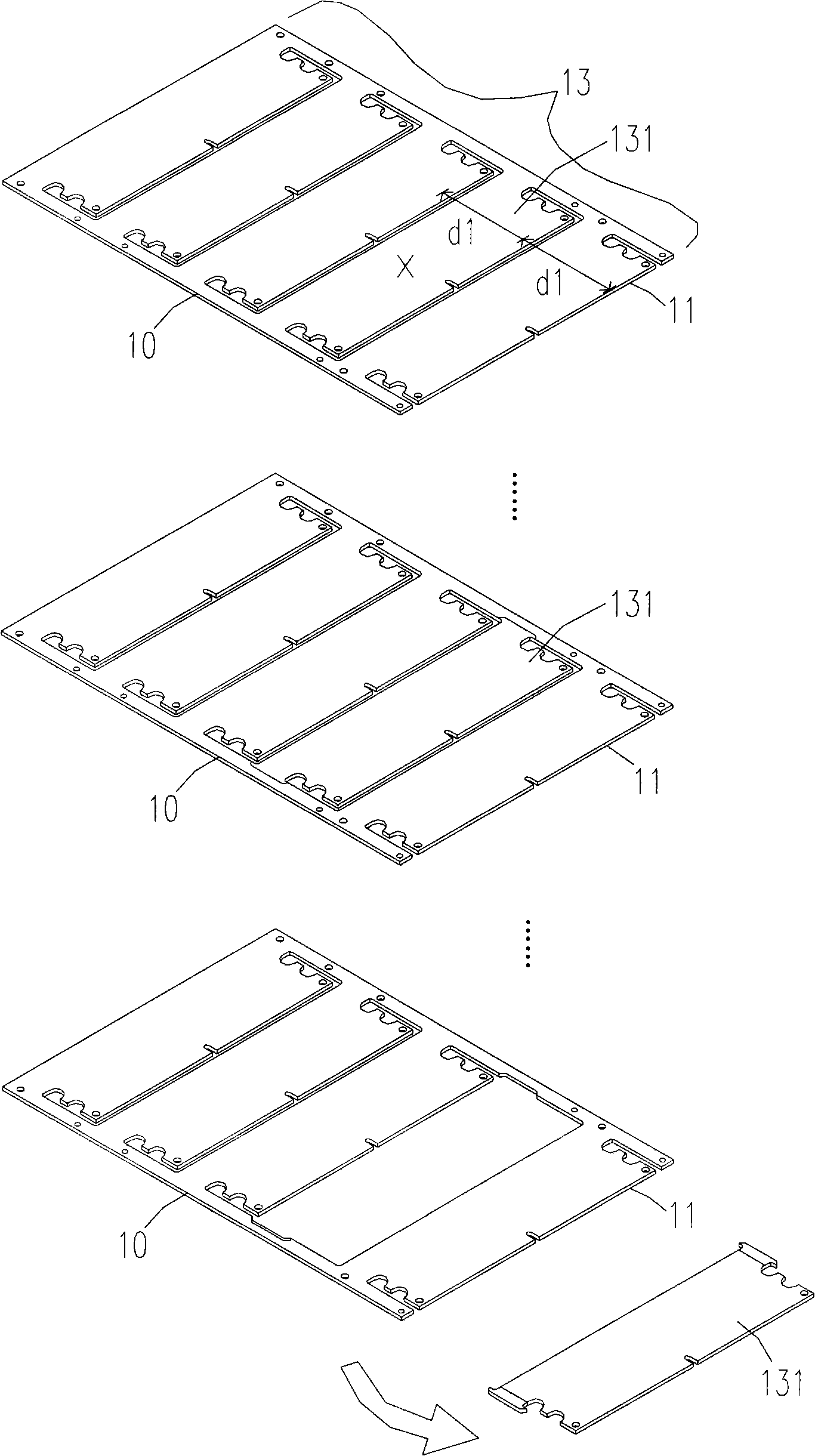
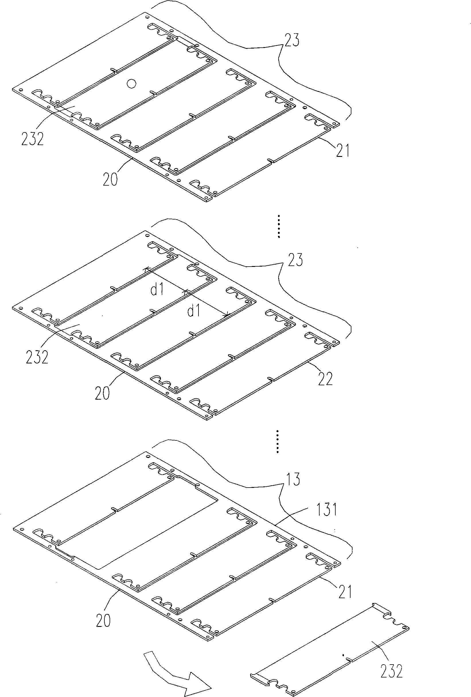
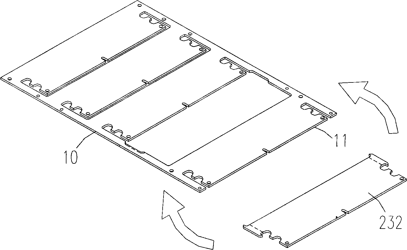
[0079] Please refer to Figure 4 ~Fig. 6, it is the schematic diagram of the first embodiment of the manufacturing method of multi-piece printed circuit board of the present invention, wherein Figure 4 It is a schematic diagram of cutting and removing an unqualified single-piece printed circuit board from a multi-piece printed circuit board to be replaced, Figure 5It is a schematic diagram of a qualified single-piece printed circuit board being cut and removed from a replacement multi-piece printed circuit board, and FIG. 6 is a schematic diagram of a qualified single-piece printed circuit board placed on a multi-piece printed circuit board to be replaced. exist Figure 4 Among them, a multi-connected printed circuit board 50 includes an upper surface 51 and a lower surface 52, which includes several single-piece printed circuit boards 53, and there ...


PUM


Abstract

The present invention provides a method for preparing multi-sheet printed circuit board, which uses a qualified single slice printed circuit board cut down from a multi-sheet printed circuit through the secondary calibration incising procedure, to replace the unqualified single slice printed circuit board on a multi-sheet printed circuit board calibrated by a secondary calibration incising procedure of the top and bottom surfaces, which can improve replacement accuracy and simplify the prior replacement procedure, so as to boost productivity effect.

Description

technical field [0001] The invention relates to a method for improving the manufacture of printed circuit boards, in particular to a method for replacing unqualified single-chip areas in the manufacturing process of multi-piece printed circuit boards. Background technique [0002] The English name of printed circuit board is Printed Circuit Board, or PCB for short. As the name suggests, printed circuit board is a circuit product made by printing technology. In the early days, circuit boards covered the surface of insulating boards by melting metal to make the required circuits. Because they can be mass-produced and the volume can be reduced, in addition to improving convenience, the price can also be reduced. After 1936, the circuit board manufacturing method was mainly to select the insulating substrate covered with metal with corrosion-resistant ink as the area, and remove the unnecessary area by etching. In recent decades, electronic products have developed rapidly. Prod...

Claims


Application Information

Patent Timeline
IPC IPC(8): H05K3/36H05K3/00
Inventor 田弘
Owner E TEEN
Why Eureka
Try Eureka