Analytical multi-spectral optical detection system

A detector and light source technology, applied in the field of multispectral fluorescence signal detection and analysis, can solve problems such as thermal control efficiency and uniformity, and achieve the effects of increasing sample processing capacity, improving compatibility, and better signal recognition

Inactive Publication Date: 2008-11-05
F HOFFMANN LA ROCHE & CO AG
View PDF10 Cites 19 Cited by
  • Summary
  • Abstract
  • Description
  • Claims
  • Application Information

AI Technical Summary

Problems solved by technology

Thermal control efficiency and uniformity are also problematic due to the presence of holes in thermal control blocks of these other designs

Method used


Image

  • Analytical multi-spectral optical detection system
  • Analytical multi-spectral optical detection system
  • Analytical multi-spectral optical detection system

Examples


Embodiment Construction

[0038] The present invention provides systems and methods for measuring multispectral signals, and in particular systems and methods for measuring multispectral fluorescent signals from one or more solid or liquid samples.

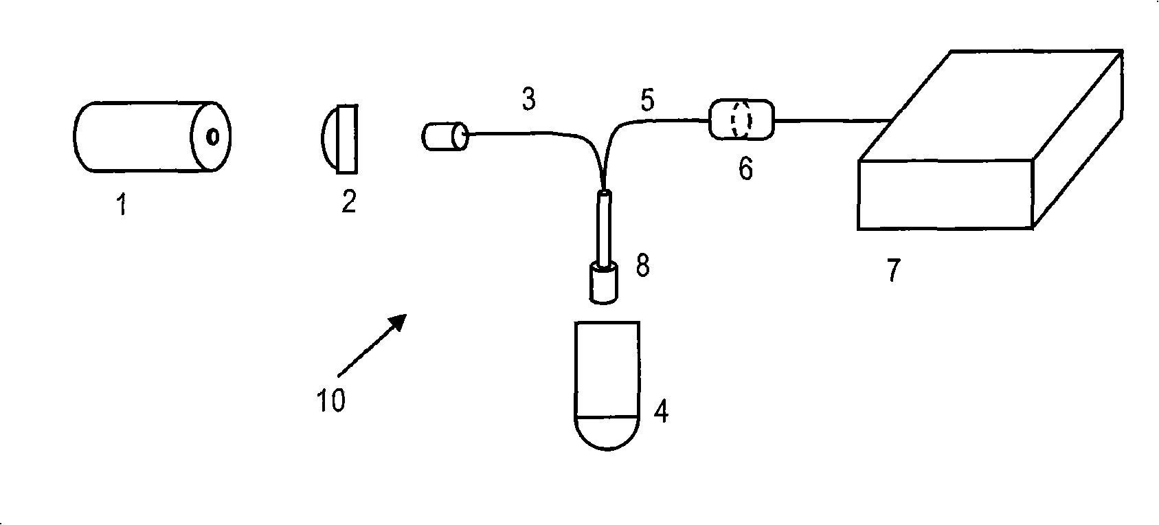
[0039] figure 1 An analytical multispectral optical detection system 10 according to an embodiment of the invention is shown. Such as figure 1 As shown, laser light from a source 1 is coupled to an optical cable 3 and sent to a sample container 4, eg for fluorescence excitation. The emitted light from the sample is then collected by the same fiber optic interface 8 . The emitted light is then filtered using a filter or series of filters to remove scattered laser light and passed to a spectrophotometer 7 or other light detection system where it is spatially separated into its component spectra. Detection is realized spatially using linear diode arrays, charge-coupled devices (CCDs), or photosensitive devices, and analyzed, for example, using function-bas...


PUM

PropertyMeasurementUnit
wavelengthaaaaaaaaaa

Abstract

Analytical multi-spectral optical detection systems and methods. A light source (1) provides one or multiple lines (e.g., discrete wavelengths) of high spectral purity excitation light that is optically coupled to a sample via delivery fiber optic cables (3) . Emission light is collected and provided to an emission detector, such as a diffraction gradient spectrophotometer emission detector (7) , using collection fiber optic cables (5) bundled with the delivery fiber optic cables in a probe interface (8) positioned proximal a sample holder (4) . The probe interface may be scanned over one or more samples, or one or more samples may be scanned proximal a fixed interface probe. Multiple excitation wavelengths allows for simultaneous excitation and detection of multiple fluorescent dyes in the visible spectrum. This increases sample throughput and reduces signal variations associated with signal acquisition at different times. The optical system provides several advantages over other systems including higher sensitivity, improved compatibility with fluorescent dyes, better signal discrimination, increased system reliability and reduced manufacturing and service costs.

Description

technical field [0001] The present invention relates generally to signal detection and analysis, and more particularly to multispectral fluorescent signal detection and analysis. Background technique [0002] Many systems are currently used to excite and detect fluorescent signals in solid or liquid samples. Examples of these systems can be found in US 6,015,674, US 5,928,907, US 6,713,297, US2002 / 0109844A1, EP 1080364B1 and EP 1080364A1. [0003] Each of these systems has flaws. For example, the use of multiple optical cables in US 6,015,674A and US 5,928,907A and the use of separate optical components for each sample in US 6,713,297B2, US 2002 / 0109844A1, EP 1080364B1 and EP 1080364A1 increases the number of optical system components. Many commercial systems also use filters to control the optical bandwidth, further increasing the number of optical components. This results in reduced detection accuracy and higher manufacturing and maintenance costs. [0004] Another lim...

Claims


Application Information

Patent Timeline
Patent Type & Authority Applications(China)
IPC IPC(8): G01N21/64G01N33/53
CPCG01N2021/6419G01N21/6428G01N21/6452G01N2021/6441G01N21/645
Inventor C·J·埃金W·M·胡弗R·T·柯尼克
Owner F HOFFMANN LA ROCHE & CO AG
Why Eureka
Try Eureka