Laminating encapsulant film containing phosphor over leds

A phosphor and sealant technology, applied in semiconductor devices, electrical solid devices, electrical components, etc., can solve the problems of inconsistent color temperature, complexity of phosphor deposition process, etc.

Active Publication Date: 2008-11-05
PHILIPS LUMILEDS LIGHTING CO LLC
View PDF0 Cites 32 Cited by
  • Summary
  • Abstract
  • Description
  • Claims
  • Application Information

AI Technical Summary

Problems solved by technology

[0006] Known or common issues with the above methods include: 1) the complexity of the phosphor deposition process; and 2) the amount of phosphor varies from LED to LED, resulting in inconsistent color temperature

Method used


Image

  • Laminating encapsulant film containing phosphor over leds
  • Laminating encapsulant film containing phosphor over leds
  • Laminating encapsulant film containing phosphor over leds

Examples


Embodiment Construction

[0024] 5 is a flowchart illustrating one embodiment of a method for wavelength conversion of LED light to produce a uniform output CCT despite LEDs emitting light having different color temperatures.

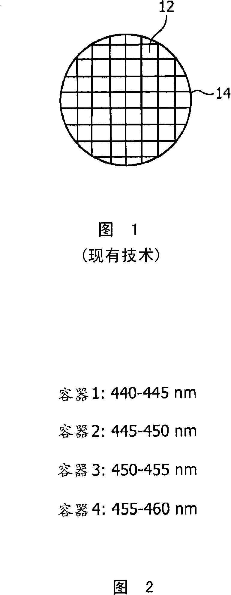
[0025] In step 10 of Figure 5, LEDs are formed on the wafer in a conventional manner. FIG. 1 is a front view of LED 12 formed on growth wafer 14 . In one embodiment, the growth wafer is sapphire, GaN or SiC, and the LEDs are CaN-based LEDs that emit blue or UV light. In other embodiments, the LED and growth substrate can be of any type. GaN-based LEDs are particularly suitable for forming blue or UV LEDs that are frequently used in combination with phosphors for wavelength conversion.

[0026] In step 16 of Figure 5, the individual LEDs are probed to energize each LED. A color detector measures the peak wavelength of light emitted from each LED. In this example, the measured color of the LED falls into one of four color ranges. Each scope is called a container. In one exam...


PUM


Abstract

A process is described for wavelength conversion of LED light using phosphors. LKD dies are tested for correlated color temperature (CCT), and binned according to their color emission. The LEDs (12) in a single bin are mounted on a single submount (24) to form an array of LEDs. Various thin sheets (51, 52, 53, 54) of a flexible encapsulant (e.g., silicone) infused with one or more phosphors are preformed, where each sheet has different color conversion properties. An appropriate sheet (51) is placed over an array of LED (12) mounted on a submount (24) , and the LEDs (12) are energized. The resulting light is measured for CCT. If the CCT is acceptable, the phosphor sheet (51) is permanently laminated onto the LEDs (12) and submount (24) . The lamination (51) encapsulates each LED (12) to protect the LEDs (12) from contaminants and damage. The LEDs (12) in the array of LEDs on the submount (24) are separated. By selecting a different phosphor sheet for each bin of LEDs, the resulting CCT is very uniform across all bins.

Description

technical field [0001] The present invention relates to light emitting diodes (LEDs), and more particularly to wavelength conversion of light from LED chips. Background technique [0002] Light emitting diodes (LEDs) can be fabricated to generate light of different colors. To produce white light, various colors can be combined. One way to generate white light from an LED structure is to deposit a yellow phosphor on top of a blue LED. There are many ways to do this. One of the most common methods is to mix phosphor particles in the encapsulant and apply it to the LED. Another method is electrophoretic deposition, where phosphor particles are deposited directly onto the LED. [0003] White light is produced when some of the blue light allowed to leak through the phosphor layer is combined with yellow light. [0004] Another way to produce white light is to combine red, green and blue light. This can be achieved by using red, green and blue LEDs, or by blue LEDs with red ...

Claims


Application Information

Patent Timeline
Patent Type & Authority Applications(China)
IPC IPC(8): H01L33/00H01L33/50H01L33/52
CPCH01L2933/0041H01L2924/0002H01L33/505H01L33/52H01L2924/00
Inventor H·钱德拉
Owner PHILIPS LUMILEDS LIGHTING CO LLC
Why Eureka
Try Eureka