
Double-frame magnetic suspension control moment gyroscope control system

A technology for controlling torque gyroscopes and control systems, applied in the field of control systems, can solve the problems of increasing control difficulty, inability to provide compensation or suppression schemes, and no precedents for magnetic bearings found

Inactive Publication Date: 2008-11-12
BEIHANG UNIV
View PDF0 Cites 41 Cited by
  • Summary
  • Abstract
  • Description
  • Claims
  • Application Information

AI Technical Summary

Problems solved by technology

The single-frame magnetic levitation CMG only has the dynamic coupling between the magnetic levitation rotor system and the frame system, the double-frame mechanical support CMG only has the dynamic coupling between the two frames, and the double-frame magnetic levitation CMG includes the above two dynamic couplings at the same time, That is, there is a dynamic coupling between the maglev rotor, the inner frame and the outer frame, which further complicates the dynamic behavior and the dynamic frame effect: First, there is an inertial coupling moment that affects each other between the maglev rotor and the inner and outer frames and gyro coupling torque, where the dynamic coupling with the outer frame not only depends on the outer frame itself, but also related to the angular displacement of the inner frame; second, there is a dynamic coupling caused by the gyro effect between the inner and outer frames, namely The interlocking phenomenon of the inner and outer frames, and this dynamic coupling not only depends on the motion of the frame, but also is related to the radial rotation of the maglev rotor; third, under the premise of not considering the nonlinearity of the bearing force, the single-frame maglev CMG is a linear system , and the dual-frame maglev CMG adds a frame degree of freedom, the gyro coupling torque is proportional to the cosine of the inner frame angular displacement, as long as the frame speed is non-zero, it becomes a nonlinear system, which increases the difficulty of control
[0005] In the prior art, if the closed-loop stiffness of the magnetic bearing is directly increased to suppress the dynamic frame effect, since the gyro torque disturbs the dynamic frame of the magnetic levitation rotor system greatly, the magnetic bearing is required to have a high stiffness correspondingly, but too high stiffness of the magnetic bearing will easily lead to The magnetic levitation system is unstable, so it is not applicable; the angular rate-current feedforward control method can be used to suppress the moving frame effect for single-frame magnetic levitation CMG, but the double-frame magnetic levitation CMG has nonlinearity, so it cannot be used
In addition, the mechanically supported CMG does not have the coupling problem between the rotor motion and the frame motion, and there is no precedent for magnetic bearings applied to two-degree-of-freedom servo-rotating electromechanical systems, so the existing technology cannot provide a reference compensation or suppression scheme

Method used


Image

  • Double-frame magnetic suspension control moment gyroscope control system
  • Double-frame magnetic suspension control moment gyroscope control system
  • Double-frame magnetic suspension control moment gyroscope control system

Examples


Embodiment Construction

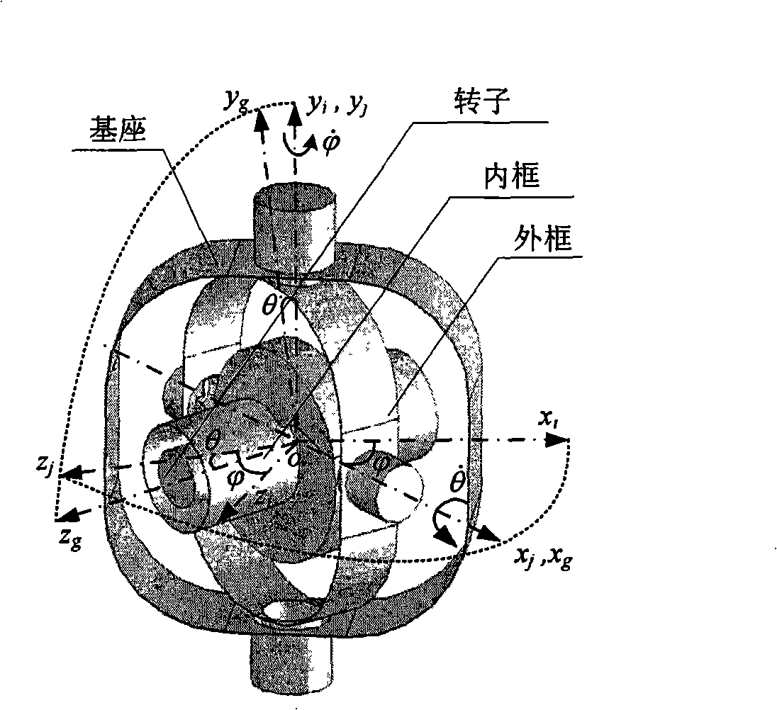
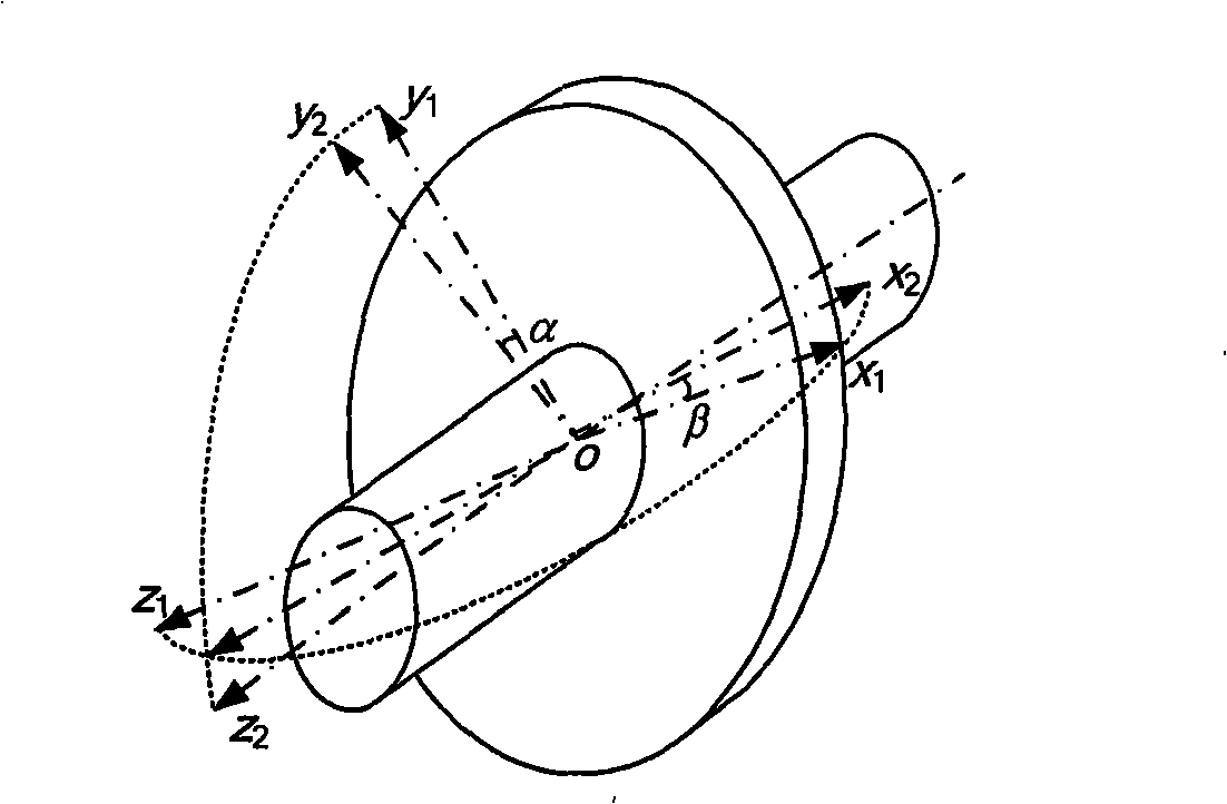
[0025] The double-frame maglev CMG body and its coordinate system are as follows: figure 1 shown. The body of the double-frame maglev CMG is composed of three parts: the rotor, the inner frame and the outer frame. The rotor is supported on the inner frame, the inner frame is supported on the outer frame, and the outer frame is supported on the base. No contact. The rotor can rotate relative to the inner frame, the inner frame is relative to the outer frame, and the outer frame is relative to the base, and the rotation axis of the inner frame is x g and frame axis y j perpendicular to each other. The fixed point o is the geometric center of the inner frame, ox i the y i z i 、ox j the y j z j and ox g the y g z g Respectively represent the base coordinate system, the outer frame coordinate system and the inner frame coordinate system. When the frame rotates, the angular displacement of the inner frame coordinate system relative to the outer frame coordinate system i...


PUM


Abstract

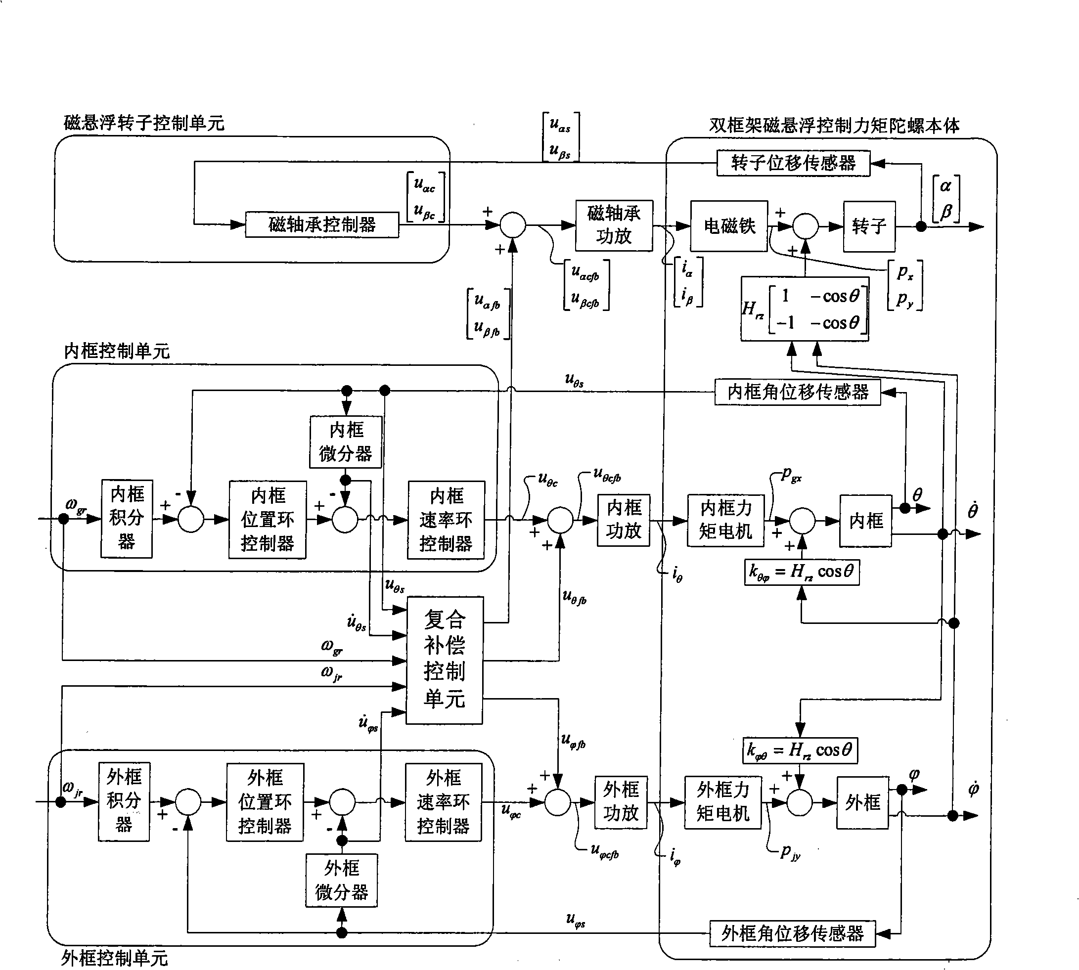
The invention relates to a double-frame magnetic-suspension CMG (Control Moment Gyroscope-CMG) control system, comprising a double-frame magnetic-suspension CMG body, a magnetic-suspension rotor control unit, an inner-frame control unit, an outer-frame control unit and a compound compensation control unit comprising a feed-forward compensator and a feed-back compensator. The feed-forward compensator carries out a feed-forward compensation for an inertia coupling disturbing moment of the rotor and the inertia moments of the inner and outer frames, and the feed-back compensator carries out the compensation for the impact of the gyroscope action disturbing moment; the outputs of the feed-forward compensator and feed-back compensator are respectively added to the outputs of the magnetic-suspension rotor control unit, inner and outer frames control units to obtain a total control value so as to realize the stable control to the double-frame magnetic-suspension CMG on the basis of compensating a dynamic frame effect. The double-frame magnetic-suspension CMG control system of the invention adopts the compensation to the output moments of magnetic bearings and frame motors to offset the coupling disturbing moment caused by the rotation of the inner and outer frames and to eliminate the displacement of the dynamic frame of the magnetic-suspension rotor, and enhances the response speed and accuracy of frames and the whole double-frame magnetic-suspension CMG.

Description

technical field [0001] The invention relates to a control system, which can be used for compensating the influence of the dynamic frame effect of the double-frame magnetic suspension control moment gyroscope on the magnetic suspension rotor system and the frame system, so as to realize the stable control of the double-frame magnetic suspension control moment gyroscope. Background technique [0002] Control moment gyroscope (Control Moment Gyroscope-CMG) is an indispensable key actuator for attitude control of long-life large spacecraft or agile spacecraft. The CMG is composed of a high-speed rotor system and a frame servo system. The high-speed rotor provides angular momentum, and the frame forces the high-speed rotor to change the direction of angular momentum, so that the CMG outputs gyro torque to adjust the attitude of the spacecraft. The number of degrees of freedom of the frame and the way the high-speed rotor is supported are the two most important factors that determ...

Claims


Application Information

Patent Timeline
Patent Type & Authority Applications(China)
IPC IPC(8): B64G1/24B64G1/28
Inventor 魏彤房建成王英广李海涛韩邦成霍甲
Owner BEIHANG UNIV
Learn More