
Postposition type sloped rotating paddle wind turbine

A tilt-rotating, wind turbine technology, applied in wind turbines, wind turbine components, wind turbines that are in the same direction as the wind, etc., can solve the problems of large horizontal thrust of vertical columns, high cost, heavy weight, etc.

Inactive Publication Date: 2008-11-12
谢晓山 +1
View PDF0 Cites 6 Cited by
  • Summary
  • Abstract
  • Description
  • Claims
  • Application Information

AI Technical Summary

Problems solved by technology

[0002] The bladed wind turbines seen at present are generally column-type wind turbines in which the blades rotate around the horizontal axis. The generator nacelle is installed horizontally on the top of the column, and the blades are placed in front of the column. The disadvantages of this layout are: When the wind intensity increases, the vertical column needs to bear a large horizontal thrust
Due to the heavy weight of the blades and power generation equipment, the vertical columns of wind turbines are mostly made of steel in the design, which is costly. In addition, the blades are placed in front of the columns, and a wind-facing device is needed to control the wind direction and stability, increasing the complexity of the organization, etc.

Method used


Image

  • Postposition type sloped rotating paddle wind turbine
  • Postposition type sloped rotating paddle wind turbine

Examples


Embodiment Construction

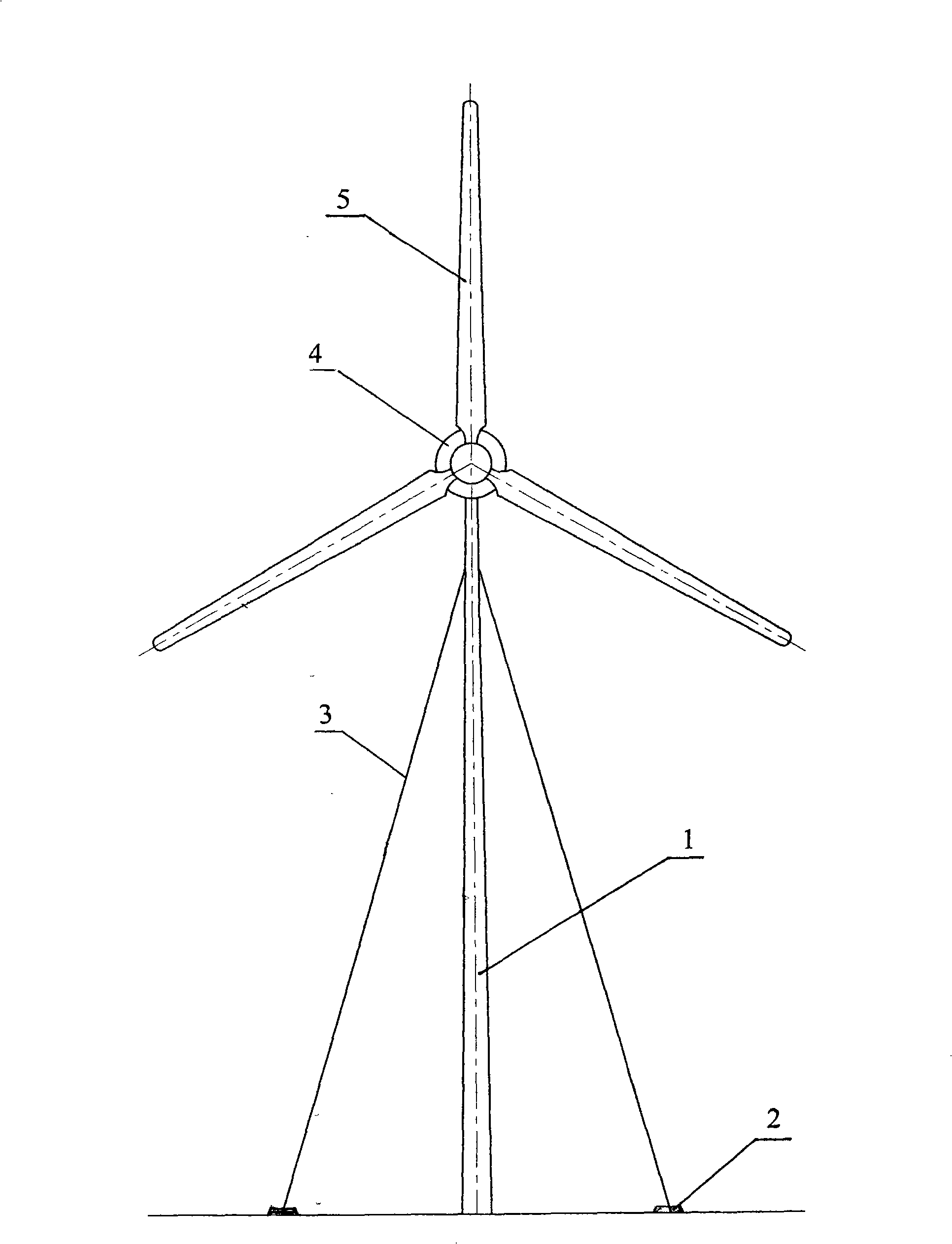
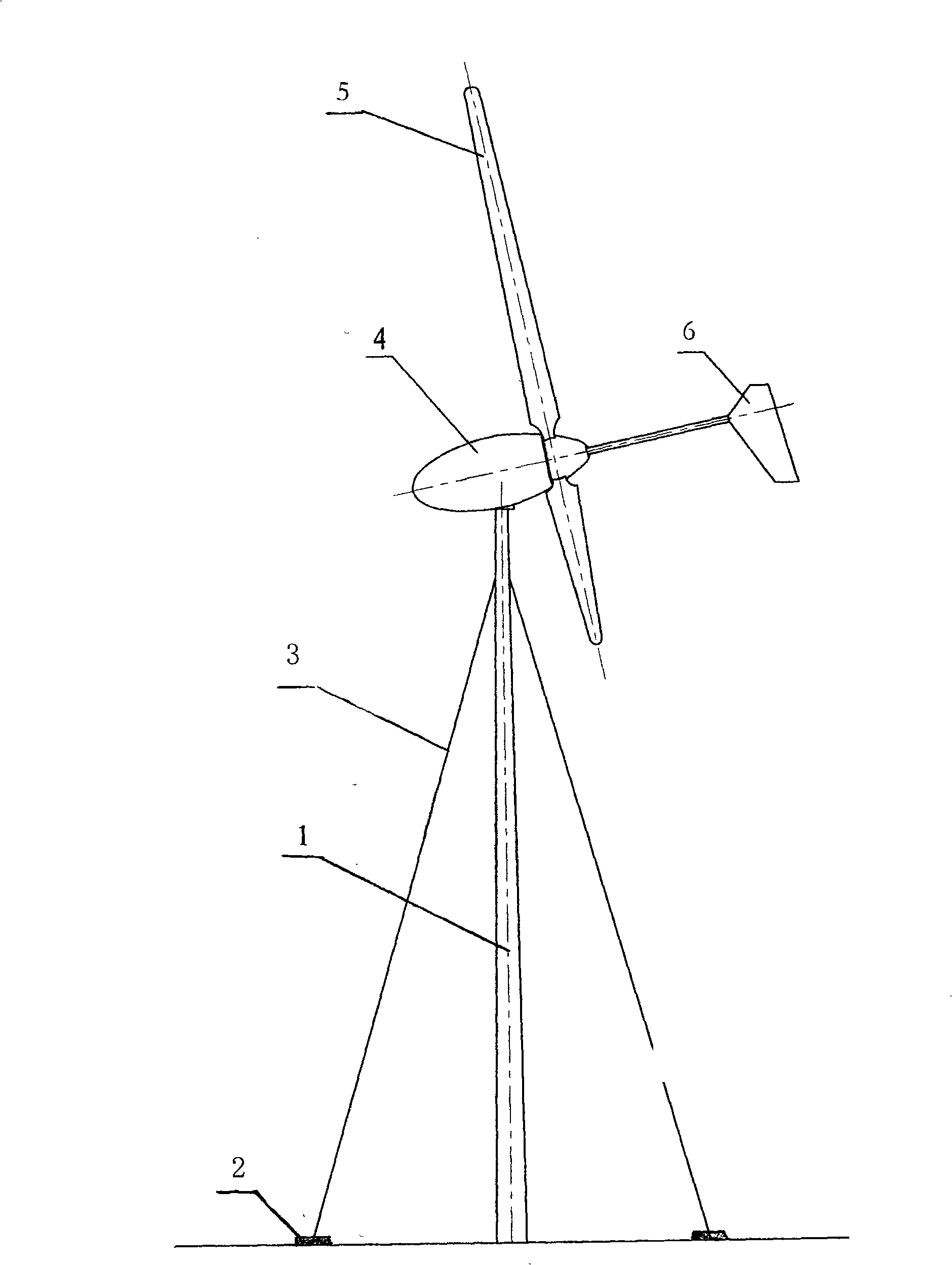
[0011] The column 1 of the present invention is vertically installed on the ground, with the root of the column 1 as the center, three ground piles 2 are arranged at equal distances around the root of the column 1, and cable-stayed steel cables 3 are arranged between the ground piles 2 on the top of the column 1. The top of 1 is inclined to set the wind turbine nacelle 4 and the equipment in the cabin. The angle between the axis of the wind turbine nacelle 4 and the ground is 30°. The wind turbine nacelle 4 rotates with an oblique axis, and the end of the wind turbine nacelle 4 behind the blade 5 is provided with a wind direction tail rudder 6 .


PUM


Abstract

The invention provides a post-typed inclined rotary oar blade wind turbine which comprises an upright post, a wind turbine cabin, oar blades and a wind direction after cabin. The wind turbine is characterized in that: more than 3 ground piles are equidistantly and evenly arranged on ground by taking the root part of the upright post as center, diagonal tightwires are arranged between the ground piles and the top of the upright post, the wind turbine cabin is installed at the top of the upright post in an inclined way, the oar blades are arranged at an end of the wind turbine cabin behind the upright post and the end tilts upwards, the oar blades rotate around an inclined shaft of the wind turbine, and the rear end of the wind turbine cabin behind the oar blades is provided with the wind direction after cabin. The wind turbine has the advantages that: the upright post is fixed by the diagonal tightwires, greatly reducing production cost and having strong wind resistance; the oar blades are arranged behind the upright post, thus facilitating wind wheels to aim at wind direction automatically and promoting stability; the oar blades are installed in the inclined way along with the wind turbine cabin, thus resulting in that the wingtips are far away from the upright post and reduce interference from flocculating flows; if the wind turbine is installed on the top of a slope or a hill, a good windward angle can be obtained as the inclined angle of the wind turbine can vertically intersected with an updraft, thus being more favorable for promoting efficiency of wind power.

Description

Technical field: [0001] The invention relates to a wind turbine, in particular to a rear-mounted tilt-rotating blade wind turbine. Background technique: [0002] The blade wind turbines seen at present are generally column-type wind turbines in which the blades rotate around the horizontal axis. The generator nacelle is installed horizontally on the top of the column, and the blades are placed in front of the column. The disadvantages of this layout are: When the wind intensity increases, the vertical columns need to bear a large horizontal thrust. Due to the heavy weight of the blades and power generation equipment, the vertical columns of wind turbines are mostly made of steel in the design, which is costly. In addition, the blades are placed in front of the columns, and a wind-facing device is needed to control the wind direction of the unit when facing the wind. stability, increasing the complexity of the organization, etc. Invention content: [0003] The object of t...

Claims


Application Information

Patent Timeline
IPC IPC(8): F03D1/00F03D11/00F03D13/20
CPCY02E10/722Y02E10/72Y02P70/50
Inventor 谢晓山梁育雄魏珏
Owner 谢晓山
Learn More