Magnetic suspension paddle distance self-adjusting vertical shaft wind power generator

A technology of wind power generators and magnetic levitation, which is applied in the direction of wind power generators, wind power motor combinations, wind power generators at right angles to the wind direction, etc. It can solve problems such as poor wind resistance, complex structure, and increased driving force of the transmission drive system, and achieve The effect of reducing starting resistance torque, improving power generation efficiency, and increasing output power

Inactive Publication Date: 2008-11-12
SHANDONG UNIV
View PDF0 Cites 16 Cited by
  • Summary
  • Abstract
  • Description
  • Claims
  • Application Information

AI Technical Summary

Problems solved by technology

However, if there are limited nails, there will be impacts, and the blades will be easily damaged under long-term, periodic and strong impacts.
[0005] At present, the most vertical-axis wind turbines using parallel connecting rods are Japan (study started in 2002), and the United Kingdom, Canada and other countries are currently under development. Most of the products in these countries use parallel connecting rods in the impeller design. , this method has high requirements on the output shaft of the generator, and the structure is relatively complicated, and there are many on-site installation procedures
In addition, from the perspective of mechanics, the greater the power of the H-type vertical axis wind turbine, the longer the blades, and the longer the distance between the center point of the parallel bar and the center point of the generator shaft, the worse the wind resistance will be.
At the same time, the traditional vertical axis wind turbine has to overcome the self-weight and friction of the transmission mechanism, and at the same time overcome the resistance caused by the self-weight of the generator rotor and the friction of the mechanical bearing, which increases the driving force of the transmission drive system and reduces the generator load. efficiency

Method used


Image

  • Magnetic suspension paddle distance self-adjusting vertical shaft wind power generator
  • Magnetic suspension paddle distance self-adjusting vertical shaft wind power generator

Examples


Embodiment Construction

[0026] The present invention will be further described below in conjunction with the accompanying drawings and embodiments.

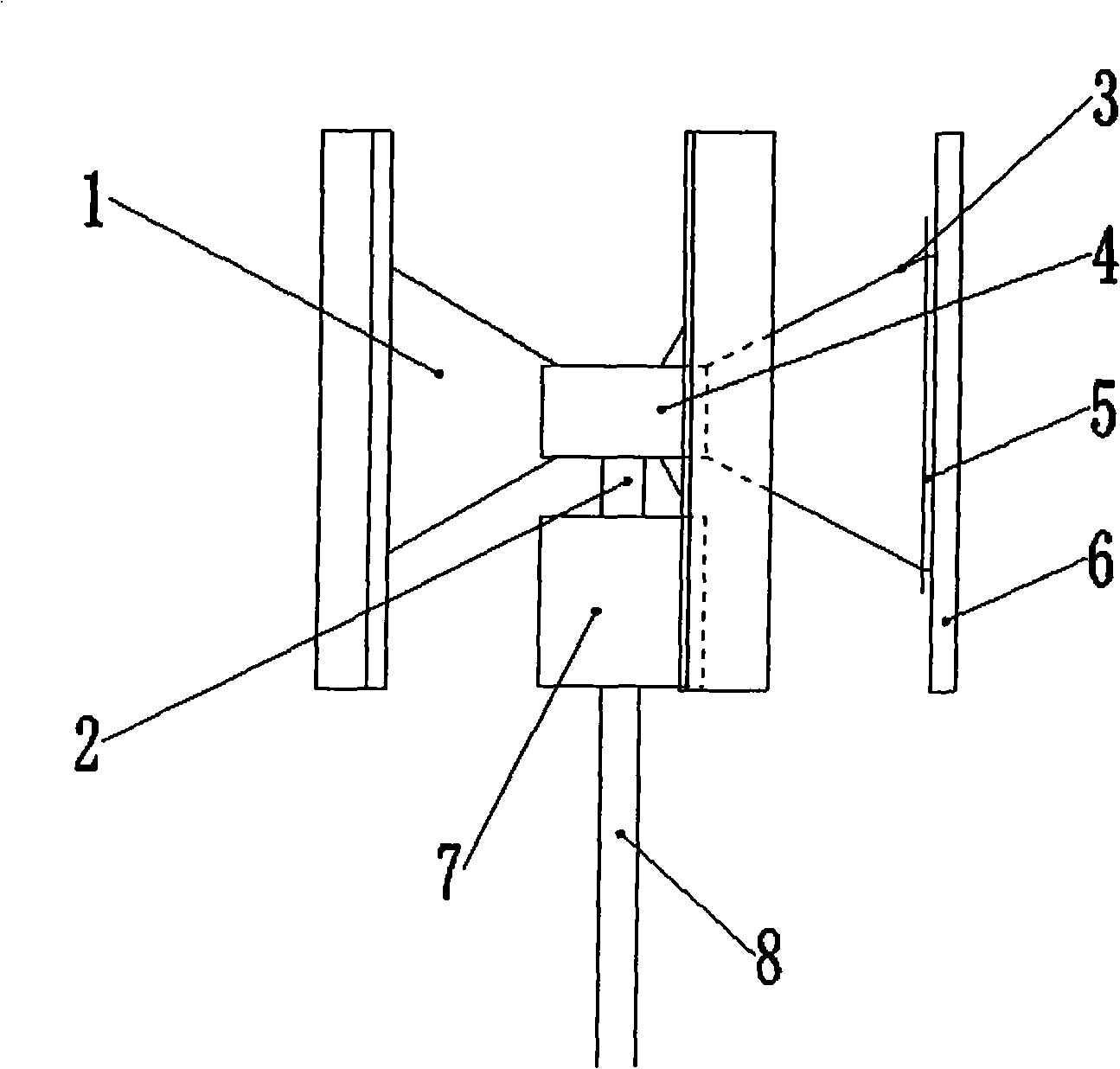
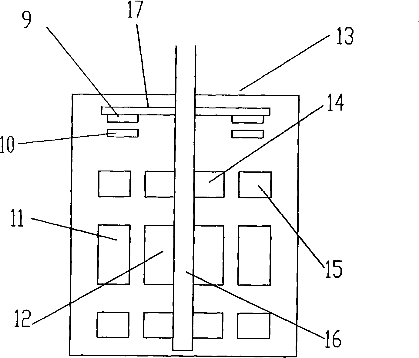
[0027] figure 1 Among them, the generator shaft 16 of the magnetic levitation wind power generator is made integrally with the impeller shaft 2 of the impeller 1, the generator shaft 16 penetrates into the motor housing 13, and the generator rotor 12 is installed on the generator shaft 16, corresponding to The generator stator 11 is arranged on the motor casing 13 of the motor, and the impeller 1 includes a plurality of blades 6, and each blade 6 is connected with a vertical vertical rod 5 through a hinge, and the vertical rod 5 is connected with two connecting rods 3, and the three become Triangular; two connecting rods 3 are fixed on the hub 4, and the hub 4 is fixedly connected with the impeller shaft 2 and drives it to rotate. The generator 7 is mounted on a tower 8 .

[0028] figure 2 Among them, the generator 7 includes a motor housing 13, and...


PUM


Abstract

The invention discloses a magnetic-suspension vertical shaft self-conditioned pitch aerogenerator which comprises a magnetic-suspension aerogenerator. A generator shaft of the magnetic-suspension aerogenerator and an impeller shaft of an impeller are integrally made. The generator shaft on which a rotor of the generator is arranged is penetrated into a motor casing on which a generator unit stator is arranged, and an axial magnetic suspension device and a radial magnetic suspension device are arranged on the generator shaft and in the motor casing for magnetic suspension positioning; the impeller shaft is arranged in a wheel hub fixedly and a plurality of blades of the impeller are connected with the wheel hub through the self-conditioned pitch device of the vertical shaft. The aerogenerator has advantages of simple structure and convenient use, effectively improves the whole performance of the aerogenerator, enhances efficiency, has energy saving, consumption reduction and environmental protection and is easy for popularization, etc.

Description

technical field [0001] The invention relates to a wind power generator, in particular to a magnetic levitation self-adjusting pitch vertical axis wind power generator. Background technique [0002] Wind turbines are classified according to the direction of the rotation axis, which can be divided into two types: horizontal axis and vertical axis. Horizontal axis wind turbines are developed and matured theoretically based on aircraft propellers, and are currently widely used. However, the design and manufacture of horizontal axis wind turbines are very complicated, and have: 1. The impeller occupies a large space and covers an area; 2. The requirements for the wind tower are high; 3. The impeller is not uniformly winded, especially the ones installed in the air The blades must also bear the huge positive pressure of the wind, so their cost is very high. The greater the power of a single machine, the greater its cost. This is one of the main factors why the price of wind power...

Claims


Application Information

Patent Timeline
Patent Type & Authority Applications(China)
IPC IPC(8): F03D9/00F03D3/06F03D7/06F03D9/25
CPCY02E10/74
Inventor 刘淑琴郭人杰边忠国薛沙沙赵闻杨洪涛
Owner SHANDONG UNIV
Why Eureka
Try Eureka