Thin film type infrared-radar beam synthesizer

A radar beam and beam synthesizing technology is applied in the field of infrared-radar beam synthesizers, which can solve the problems of affecting test accuracy, large radar waves, and the inability of beam synthesizers to move with the simulator, and achieves high infrared reflectivity and radar waves. The effect of high transmittance

Active Publication Date: 2008-11-12
深圳市睿诚光电科技有限公司
View PDF0 Cites 16 Cited by
  • Summary
  • Abstract
  • Description
  • Claims
  • Application Information

AI Technical Summary

Problems solved by technology

[0004] In order to solve the problem that the existing beam combiner produces a large IPD (insertion phase delay) to the radar wave, which affects the test accuracy and the existing beam combiner cannot move with the simulator, it provides a thin-film infrared sensor. - Radar beamformer

Method used


Image

  • Thin film type infrared-radar beam synthesizer
  • Thin film type infrared-radar beam synthesizer
  • Thin film type infrared-radar beam synthesizer

Examples


specific Embodiment approach 1

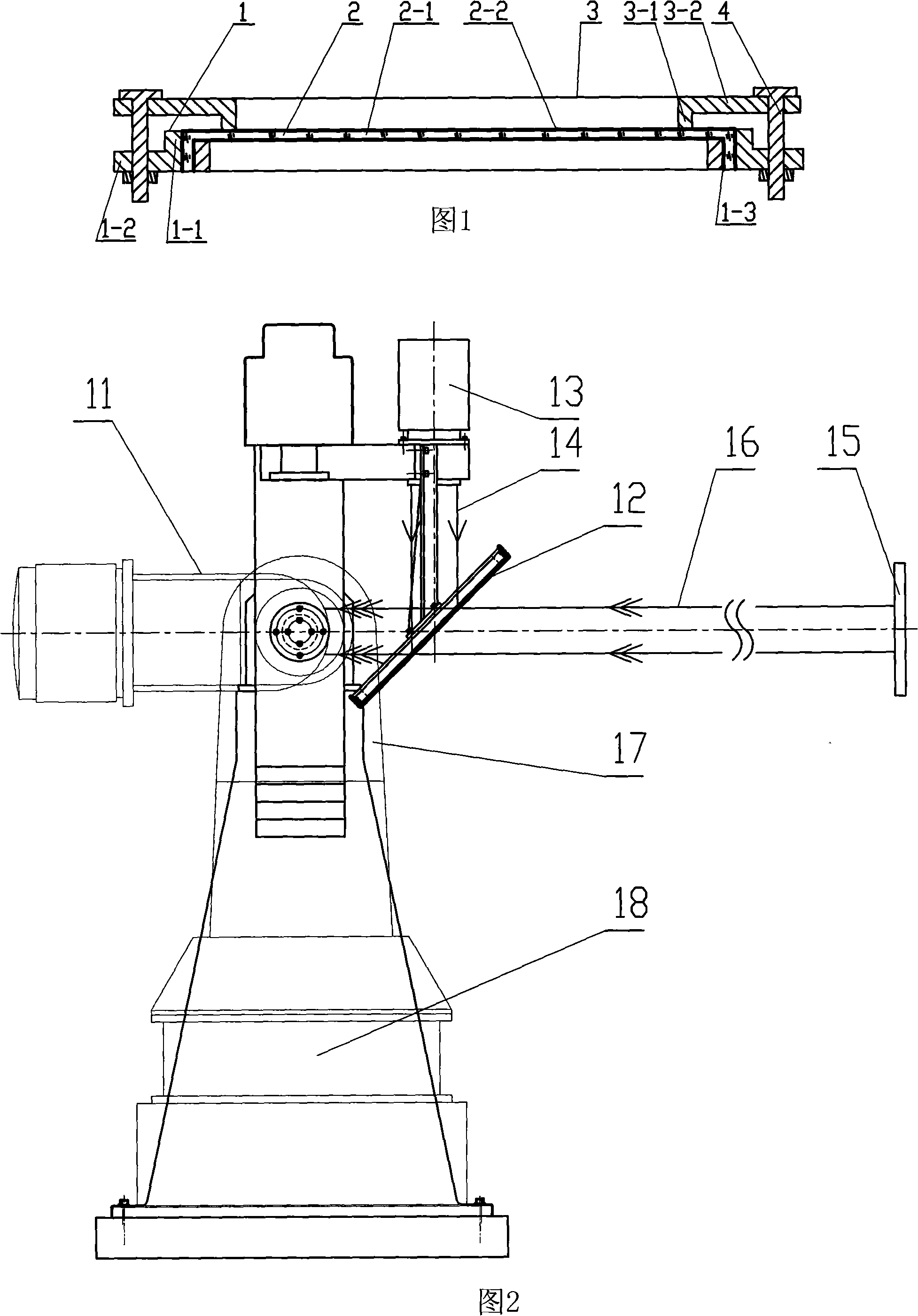
[0008] Specific Embodiment 1: This embodiment is described in conjunction with FIG. 1. The thin-film infrared-radar beam combiner described in this embodiment is composed of a fixed adjustment mechanism and a beam synthesis film 2, and the beam synthesis film 2 is fixed on the fixed adjustment mechanism. superior.

specific Embodiment approach 2

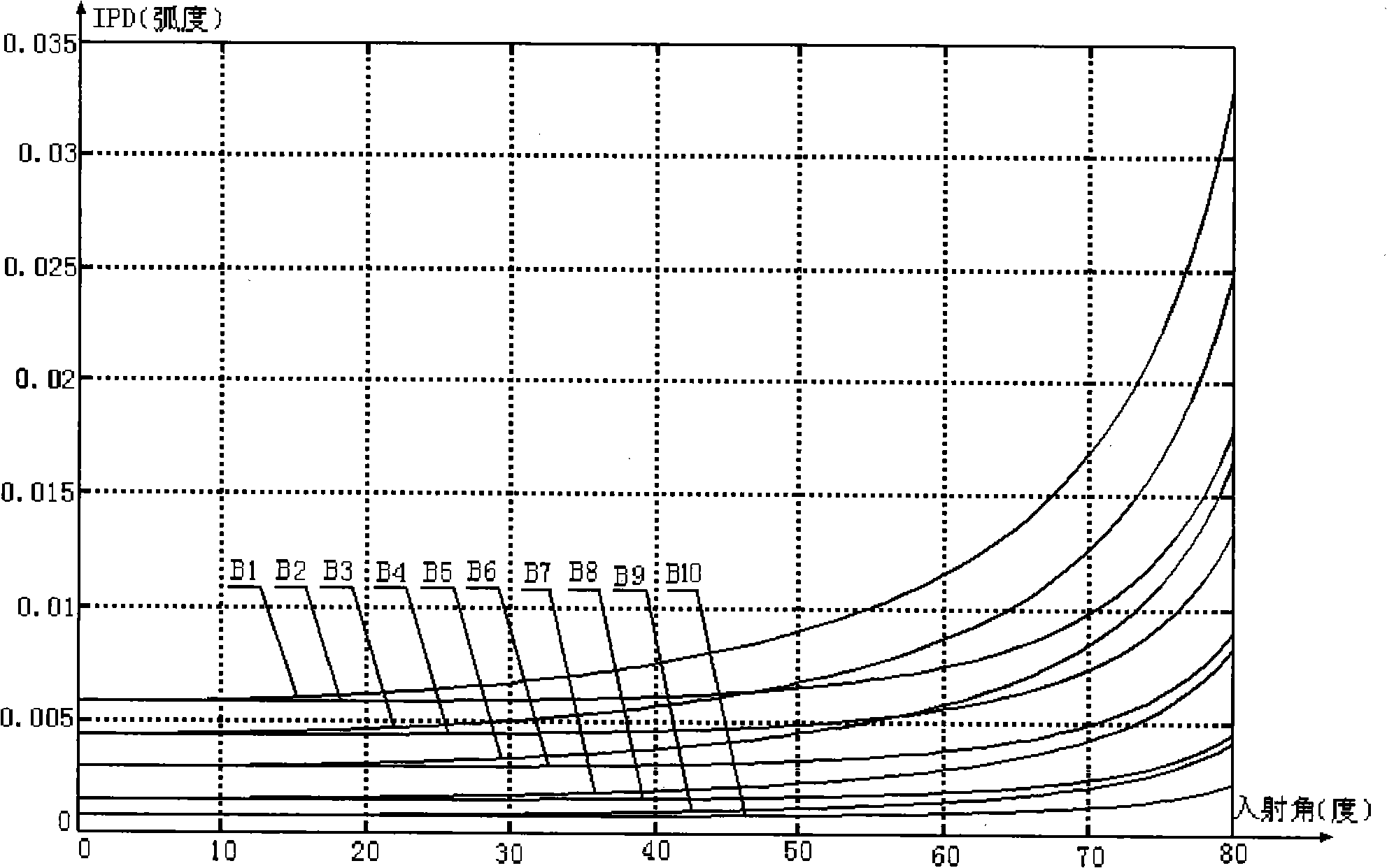
[0009] Embodiment 2: The thickness of the beamforming film 2 in this embodiment is 0.005mm-1mm. In order to reduce the IPD value and its difference in the horizontal and vertical directions, the thickness of the beamformer should be reduced as much as possible. Considering the processing technology and processing level of the non-metallic film and the comprehensive factors in the fixing process of the beamformer, the final thickness of the beamformer is selected at 0.05mm in practice. Other compositions and connections are the same as in the first embodiment.

specific Embodiment approach 3

[0010] Specific embodiment three: This embodiment is described in conjunction with FIG. 1. The beamforming film 2 in this embodiment is composed of a dielectric substrate 2-1 and a dielectric reflection film layer 2-2. The dielectric reflection film layer 2-2 is attached to on the outer surface of the dielectric substrate 2-1. Other compositions and connections are the same as in the first embodiment.


PUM


Abstract

A diaphragm type infra-red radar beam synthesizer relates to an infra-red radar beam synthesizer. The synthesizer of the invention solves the problems that the existing beam synthesizer produces comparatively large IPD (Insertion Phase Delay) to radar wave, thus leading to an impact on the testing precision and causing the existing beam synthesizer to be incapable of moving with a simulator. The beam synthesizer of the invention consists of a fixing adjustment mechanism, a beam synthesizing film (2); the beam synthesizing film (2) is fixedly arranged on the fixing adjustment mechanism. The synthesizer of the invention produces a small amount of IPD to radar wave and can move with an infrared simulator with high radar wave transmittance rate and infrared reflectivity rate.

Description

technical field [0001] The invention relates to an infrared-radar beam combiner. Background technique [0002] With the development of composite precision guidance technology, infrared-radar composite guidance has become a hot spot in the research and development of countries all over the world due to its advantages of long operating distance, high guidance precision and strong anti-interference ability, and the corresponding simulation test system has also become a research hotspot in countries all over the world. , and the infrared-radar beam combiner is the key technology in the simulation test system. Its function is to reflect infrared waves and transmit radar waves. It acts as a mirror for infrared signals and transmits radar signals. The transmittance should be as high as possible, while ensuring a small IPD (insertion phase delay) for radar waves, especially within the range of the radar seeker, and not interacting with radar targets to cause interference, ensuring t...

Claims


Application Information

Patent Timeline
Patent Type & Authority Applications(China)
IPC IPC(8): G01S7/00
Inventor 康为民
Owner 深圳市睿诚光电科技有限公司
Why Eureka
Try Eureka