Optical pickup

A technology of optical pickups and optical discs, applied to instruments, optical recording/reproduction, head configuration/installation, etc., to achieve the effect of simple structure

Inactive Publication Date: 2008-11-12
PANASONIC CORP
View PDF2 Cites 0 Cited by
  • Summary
  • Abstract
  • Description
  • Claims
  • Application Information

AI Technical Summary

Problems solved by technology

When the inclination of the objective lens 101 is adjusted with a jig different from that of the optical pickup without using the two adjustment screws 110a, 110b, the adjustment screws 110a, 110b and the screw holes 108b1, 108b2 of the actuator base 108 are unnecessary. , but it is necessary to set up an additional mechanism that can adjust the tilt towards the two-axis directions of the tangential direction 115 and the radial direction 116

Method used


Image

  • Optical pickup
  • Optical pickup
  • Optical pickup

Examples


no. 1 Embodiment approach

Embodiments of an optical pickup according to the present invention will be described below with reference to the drawings.

[0035]

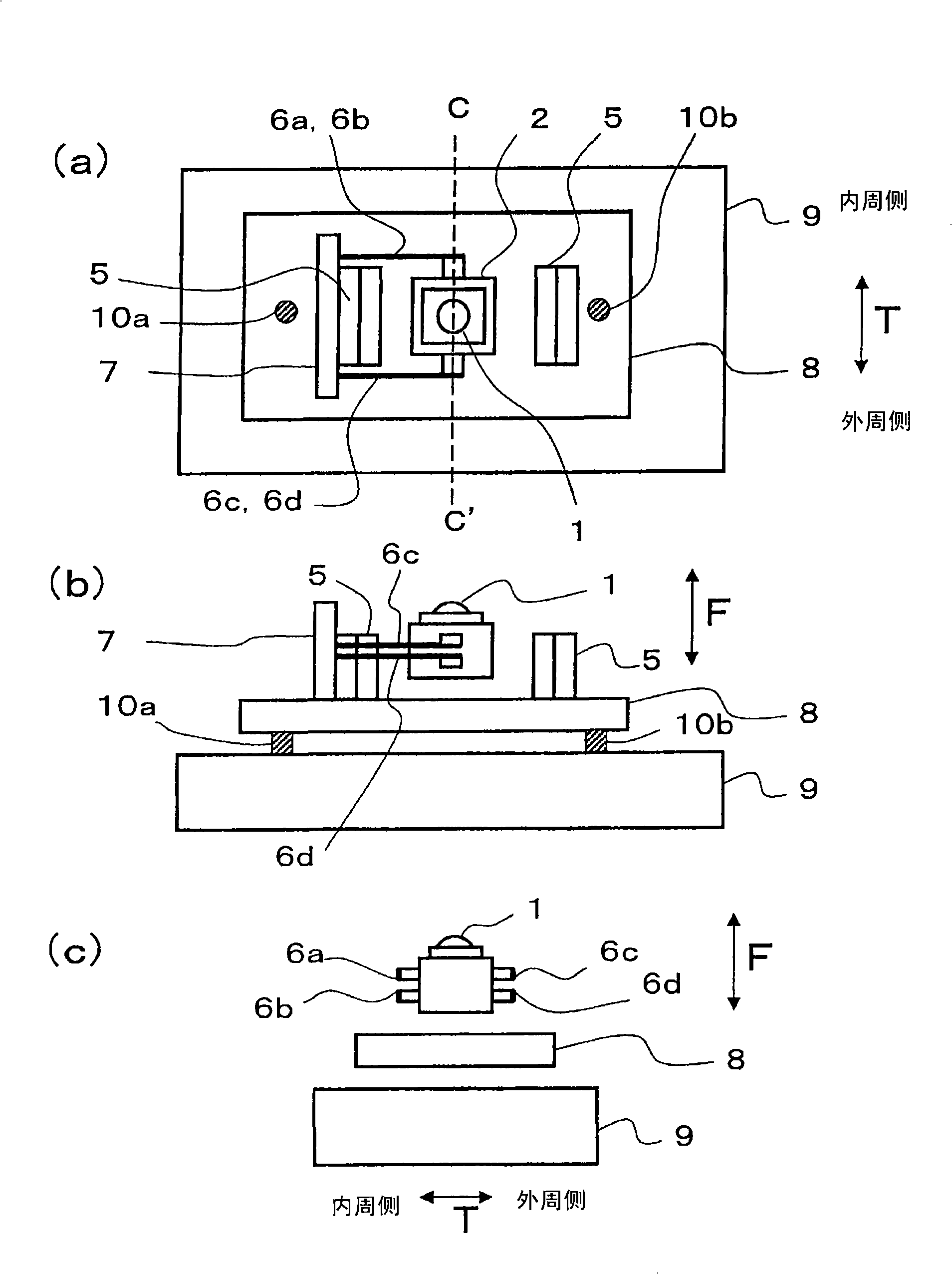
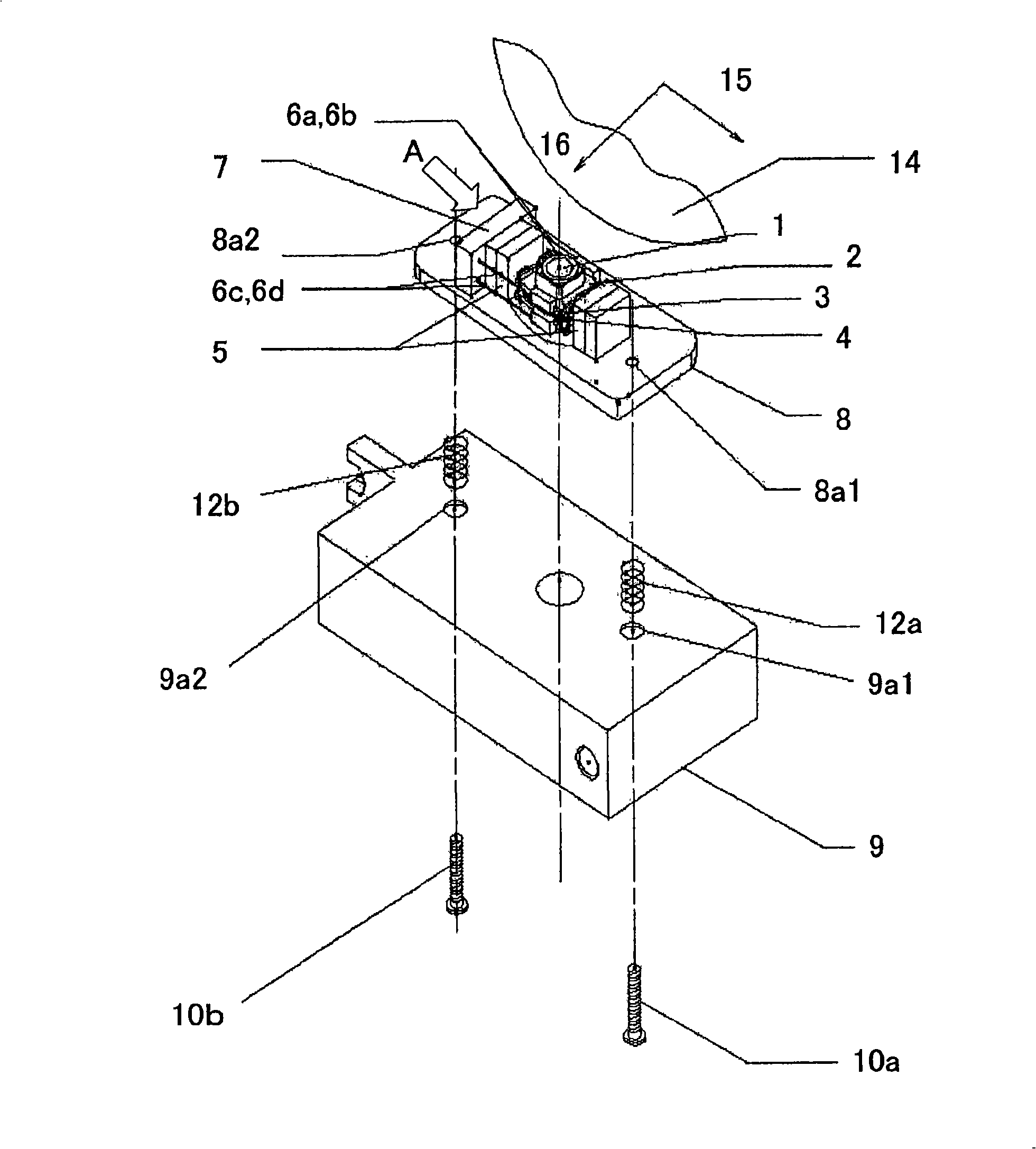
First, refer to figure 1 and figure 2 . figure 1 (a) is a plan view of the optical pickup of this embodiment, figure 1 (b) is from figure 1 (a) The side view viewed from line C~C', figure 1 (c) is figure 1 Cross-sectional view of line C to C' in (a). in addition, figure 2 It is an exploded perspective view of the optical pickup of this embodiment.

[0036]

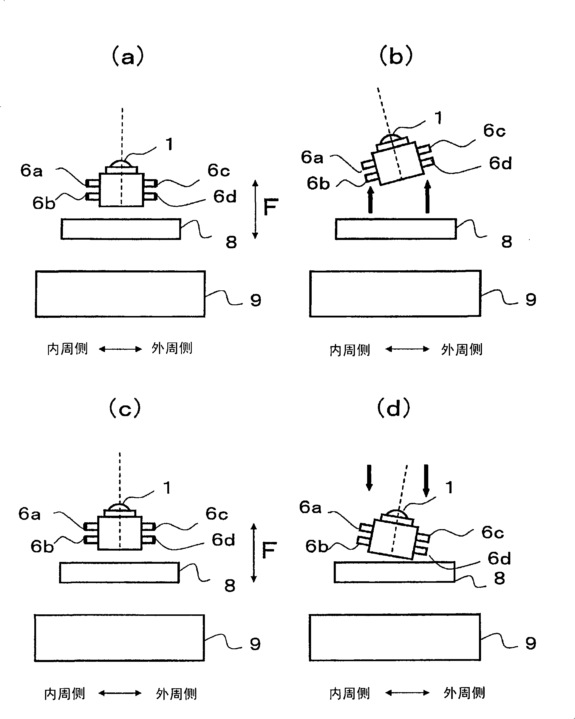
figure 1 The shown optical pickup includes an actuator base 8 and an objective lens 1 supported by the actuator base 8 via four suspension wires 6a, 6b, 6c, and 6d. The objective lens 1, under the effect of the following lens driving mechanism (lens actuator), can resist the elastic force of the suspension wires 6a, 6b, 6c, 6d. bit. This displacement of the objective lens 1 is carried out in accordance with the instructions of the control unit in the optical disc device d...


PUM


Abstract

An optical pickup having an objective lens (1) for collecting a laser beam on a signal surface of an optical disk (14), lens actuators (3, 4, 5) capable of moving the objective lens (1) at least in the direction vertical to the signal surface of the optical disk (14), an actuator base (8) for supporting the lens actuators (3, 4, 5), regulation mechanisms (10a, 10b) etc. for defining the height of the actuator base (8) in the optical pickup and also defining the tilt angle of the actuator base (8) in a tangential direction (15) of the optical disk (14), and tilt generation mechanisms (6a, 6b, 6c, 6d) for varying the tilt angle of the objective lens (1), the variation being in the radial direction of the optical disk and being performed according to the height of the objective lens (1) relative to the actuator base (8).

Description

technical field [0001] The present invention relates to an optical pickup for recording and reproducing information recording media such as optical discs by irradiating light beams such as laser beams. Background technique [0002] In an optical disc device, in order to optically record data on a rotating optical disc or optically read data from a rotating optical disc, it is necessary to irradiate a light beam to a target portion on the optical disc, that is, a track. When irradiating light beams, a small "optical pickup" with a built-in light source and light receiving element is used. [0003] The optical pickup is a part of the optical disc device, and can linearly reciprocate along the radial direction of the optical disc provided by the disc motor in the optical disc device, and accesses an arbitrary track of the optical disc. [0004] The optical pickup includes: a semiconductor laser that radiates a light beam as a light source; an objective lens that focuse...

Claims


Application Information

Patent Timeline
IPC IPC(8): G11B7/08G11B7/095
CPCG11B7/0932G11B7/082
Inventor 植田泰雄高桥耕介高桥宏昌伴武臣
Owner PANASONIC CORP
Why Eureka
Try Eureka