

Thermal transfer coating
A heat transfer and coating technology, applied in the direction of coating, metal material coating process, heat transfer modification, etc., can solve the problems of difficult to achieve thickness control, poor overall thermal conductivity of the coating, etc.
Inactive Publication Date: 2008-11-12
3M INNOVATIVE PROPERTIES CO
View PDF2 Cites 9 Cited by
- Summary
- Abstract
- Description
- Claims
- Application Information
AI Technical Summary
Problems solved by technology
These coatings typically have poor bulk thermal conductivity and thus require precise thickness control, which is difficult to achieve on substrates with three-dimensional surfaces
Method used
View moreImage
Smart ImageViewing Examples

Examples
example
[0072] Examples 1 to 9 were prepared and tested as described above. The coating materials, coating process and test methods used are summarized in Table 1. The heat transfer coefficient versus heat flux for Examples 1 to 8 was measured using 3M NOVEC HFE-7000 as the working fluid. The results are shown in Figure 5-7 middle.
[0073] Table 1
[0074]
[0075] While the heat transfer coatings described above are typically capable of dissipating 30-45 watts / cm2 before reaching CHF, the heat exchanger in Example 9 was able to dissipate 89 watts / cm2 with a 30 cm hydraulic head applied to the inlet.
Login to View More PUM
| Property | Measurement | Unit |
|---|---|---|
| The average diameter | aaaaa | aaaaa |
| Thickness | aaaaa | aaaaa |
Abstract
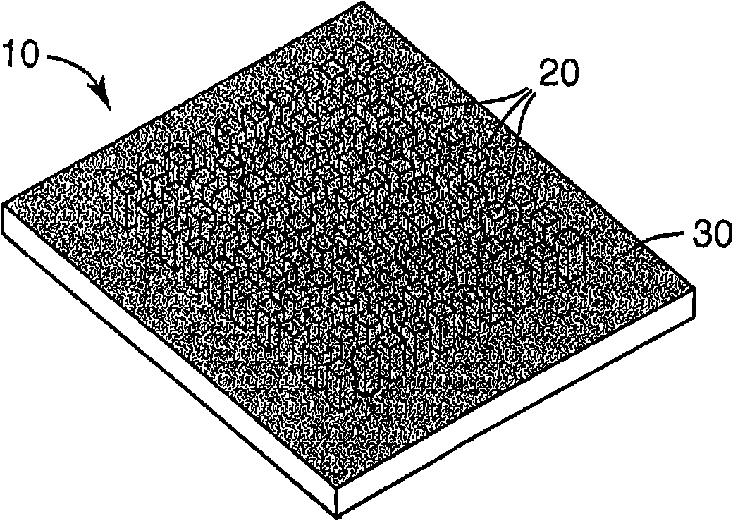
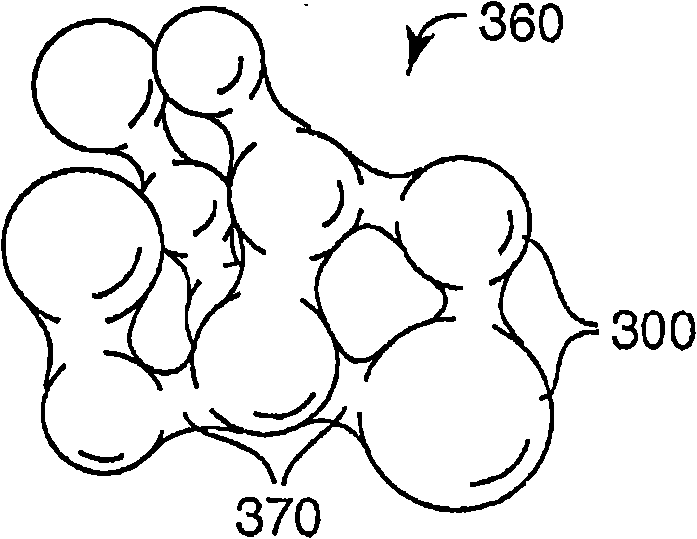
The present invention discloses a thermal transfer coating comprising a plurality of metal bodies and a plurality of interstitial elements disposed between and connecting the plurality of metal bodies to one another. The metal bodies comprise an inner portion comprising a first metal and an outer portion comprising an alloy comprising the first metal and a second metal. The interstitial elements comprise the alloy of the outer portion.
Description
technical field [0001] The present invention generally relates to thermal transfer coatings. More specifically, the present invention relates to porous metal coatings and methods of making and using the coatings. Background technique [0002] A cooling system for a heat dissipating element comprising an evaporable or boilable fluid. The resulting steam is then condensed using external means and returned to the boiler. In order to improve the heat transfer properties of the fluid at the boiler, porous boiling surfaces may be used. [0003] A variety of porous boiling surfaces are available, including, for example, coatings produced by flame or plasma spraying. But controlling porosity and uniformly coating three-dimensional substrates can be difficult using these processes. Other known coatings include conductive particles combined with an organic binder. These coatings generally have poor bulk thermal conductivity and thus require precise thickness control, which is dif...
Claims
Login to View More Application Information
Patent Timeline
 IPC IPC(8): H05K7/20
CPCH01L23/3736C23C28/00C23C28/023F28F13/187H01L23/3732H01L23/3733C23C26/00H01L23/427C23C28/321C23C28/322C23C28/341H01L2924/0002Y10T428/25Y10T428/2991Y10T428/256H01L2924/00C22F1/00
Inventor菲利普·E·图玛加里·M·帕尔姆格伦
Owner3M INNOVATIVE PROPERTIES CO