Dust separation cup of suction cleaner

A technology of dust separation and vacuum cleaner, applied in the direction of suction filter, etc., to achieve the effect of avoiding secondary pollution

Active Publication Date: 2008-11-19
宁波大华电器有限公司
View PDF1 Cites 15 Cited by
  • Summary
  • Abstract
  • Description
  • Claims
  • Application Information

AI Technical Summary

Problems solved by technology

And there is no shielding mechanism in the lower part, and the high-speed airflow ca

Method used


Image

  • Dust separation cup of suction cleaner
  • Dust separation cup of suction cleaner
  • Dust separation cup of suction cleaner

Examples


Example Embodiment

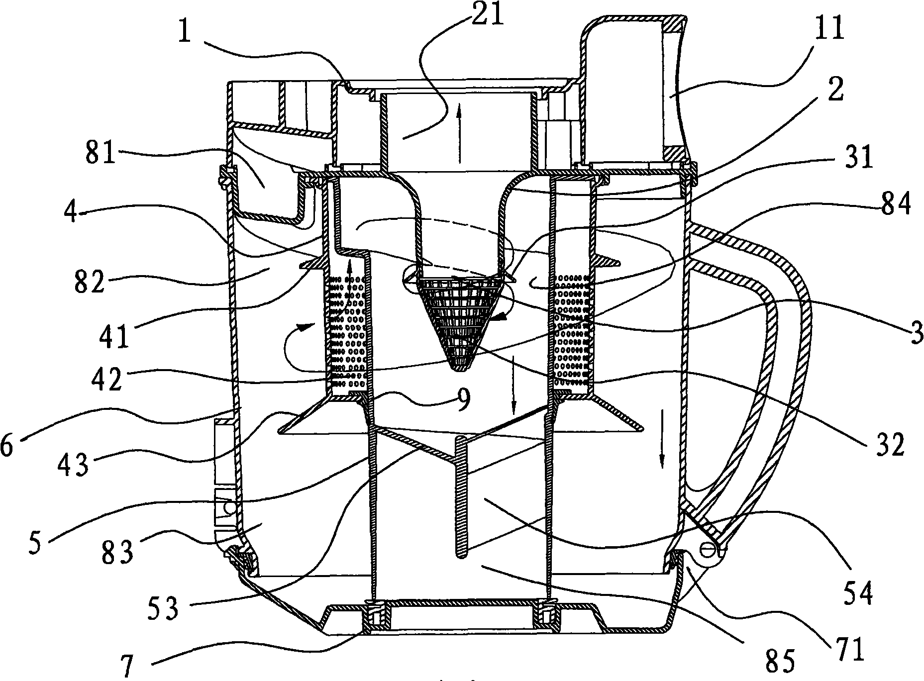
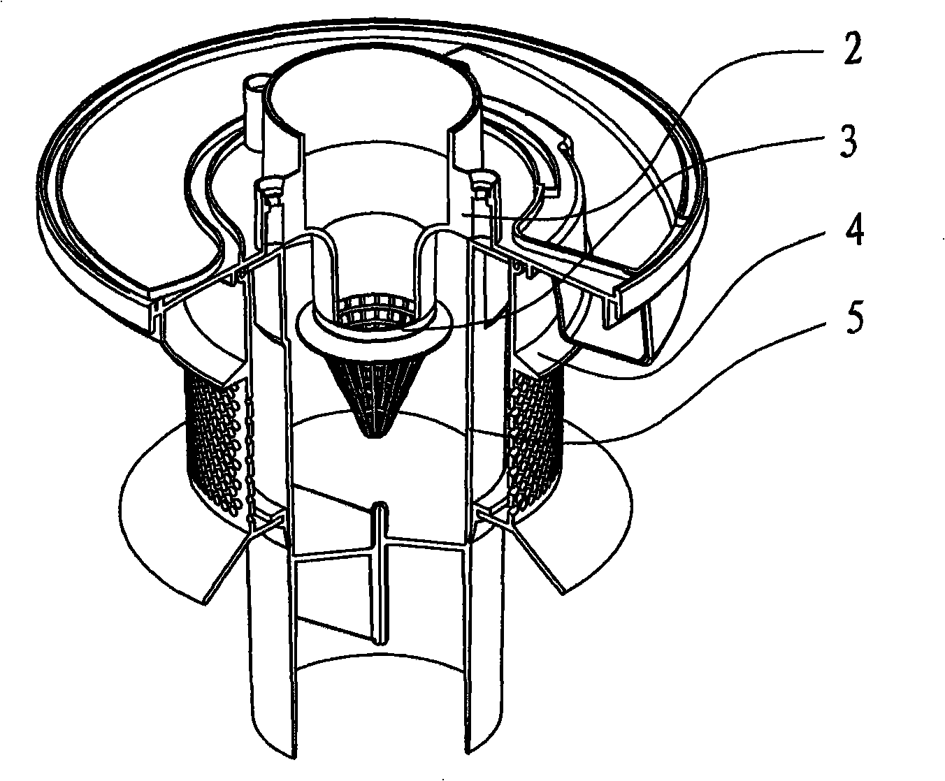
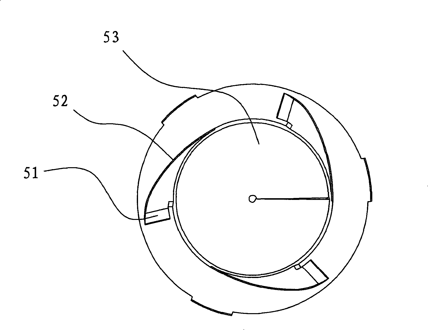
[0023] Example: refer to Figure 1 to Figure 5 , a dust separation cup for vacuum cleaners, comprising a cup body 6 shaped like a cup, a cup base 7 connected with the bottom edge of the cup body 6, and a cup cover base 2 connected with the top edge of the cup body 6, connected to the cup cover base 2. The cup cover 1 on the upper side, and the air outlet 21 formed by the cup cover base 2 and the center of the cup cover, are equipped with a first-stage dust separator 4 with a vent on the lower side of the cup cover base 2, and the first-stage dust separation The lower side of the dust separator 4 extends outwardly of the dust ring 43, and the upper end of the first-stage dust separator 4 is installed through the inner side and is provided with three cyclone ducts 5 with helical air inlet channels. The upper part of the inner cavity of the cyclone is provided with a secondary dust separator 3 with an upper end opening with a secondary filter screen 32 and a non-opening lower end...


PUM


Abstract

The invention discloses a dust separation cup for a dust collector, which comprises a cup body, a cup bottom, a cup cover base, a cup cover, a primary dust separator on the lower side of the cup cover base, a dust isolation ring at the lower part of the primary dust separator, a cyclone barrel comprising at least one spiral air incoming channel arranged at the upper end on the inner side, an air inlet of a spiral air incoming channel formed by the lateral surfaces of the cup cover and the cup cover base, and an air outlet consisting of the cup cover base and the cup cover. The dust separation cup is characterized in that a tapered secondary dust separator with a filter mesh is arranged on the upper part of the inner cavity of the cyclone barrel, and a guide ring is arranged on the outer side of the upper edge. A guide ring is also arranged at the middle part of the primary dust separator, and a screw rod mechanism is also arranged at the lower part of the cyclone barrel. The screw rod mechanism includes a helical blade, and one end of the helical blade extends downwards to form a dust stop baffle. By arranging the filter meshes in the primary and the secondary dust separators, the guide rings on the lateral surfaces and the screw mechanism in the cyclone barrel, the air is boosted twice and filtered uniformly in the inner cavity of the dust separation cup of the dust collector, thus effectively avoiding the problem of secondary pollution.

Description

technical field [0001] The invention relates to a dust separation device, in particular to a dust separation cup for a vacuum cleaner. Background technique [0002] Most of the vacuum cleaners currently on the market use the principle of centrifugal cyclone to separate air and dust, but the separation effect is generally not good, and the fine dust is easily discharged with the air to cause secondary pollution. [0003] The patent number is 200620105888.6, and the Chinese patent titled "Secondary Cyclonic Separation Cup for Vacuum Cleaner" discloses a technology for secondary cyclone separation cup for vacuum cleaners. It includes a cup, an air outlet on the cup, and A tangential air inlet on the peripheral wall of the cup body and a separator located in the cup body, the separator is provided with an outer cylinder connected to the connecting bracket and the isolation cover, and the separator air inlet lower than the air inlet of the cup body is opened on the peripheral wal...

Claims


Application Information

Patent Timeline
IPC IPC(8): A47L9/16
Inventor 罗建元张波
Owner 宁波大华电器有限公司
Why Eureka
Try Eureka