
Column plate downcomer for evenly distributing liquid stream

A technology of uniform distribution and downcomer, applied in the field of downcomer, can solve the problems of long liquid residence time, increased liquid outlet resistance at the bottom of the downcomer, low flow rate, etc.

Inactive Publication Date: 2010-08-18
NANJING UNIV
View PDF3 Cites 0 Cited by
  • Summary
  • Abstract
  • Description
  • Claims
  • Application Information

AI Technical Summary

Problems solved by technology

This method has a certain effect, but because the flow velocity on both sides of the mass transfer area is smaller than that in the middle, under the same flow conditions, the liquid residence time on both sides is still longer, so there is still the possibility of "small vortex area"
In addition, the inlet distribution plate increases the resistance of the liquid outlet at the bottom of the downcomer, and the large flow downcomer is prone to flooding

Method used


Image

  • Column plate downcomer for evenly distributing liquid stream
  • Column plate downcomer for evenly distributing liquid stream
  • Column plate downcomer for evenly distributing liquid stream

Examples


Embodiment 1

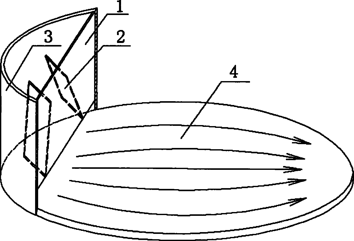
[0035] For a tray with an inner diameter of 600mm, its downcomer is as shown in Figure 2, and its downcomer plate 1 is 800mm wide, 1100mm long, and 3mm thick. Splitter 2 has a thickness of 2 mm, a width of 80 mm, and a length of 270 mm. The angle θ between it and the tray 4 is 75°, and the angle α between it and the downcomer plate 1 is 60°. The narrowest part of the splitter 2 from the tower wall 3 is 6mm, and the widest part is 26mm. The bottom of the downcomer plate 1 is in a zigzag arc shape, and the length is 440mm.

Embodiment 2

[0037] For a tray with an inner diameter of 600mm, its downcomer is as shown in Figure 5, and its downcomer plate 1 is 800mm wide, 1100mm long, and 3mm thick. Divider plate 2 has a thickness of 2 mm, a width of 80 mm, and a length of 270 mm. The angle θ between it and the tray 4 is 75°, and the angle α between it and the downcomer plate 1 is 90°. The narrowest part of the splitter plate 2 from the tower wall 3 is 6 mm, and the widest part is 20 mm. The bottom of the downcomer plate 1 is smooth and arc-shaped, and the length is 440mm.

Embodiment 3

[0039] For a tray with an inner diameter of 600mm, its downcomer is as shown in Figure 6, and its downcomer plate 1 is 800mm wide, 1100mm long, and 3mm thick. Divider plate 2 has a thickness of 2 mm, a width of 80 mm, and a length of 270 mm. The angle θ between it and the tray 4 is 75°, and the angle α between it and the downcomer plate 1 is 90°. The narrowest part of the splitter 2 from the tower wall 3 is 6mm, and the widest part is 20mm. The bottom of downcomer plate 1 is a zigzag trapezoid, with a top length of 200 mm and a height of 70 mm. Wherein the welding direction of the splitter plate 2 intersects with the waist of the trapezoid.


PUM


Abstract

A column plate downcomer for evenly distributing liquid flow is mainly composed of a downcomer plate, a tower inner wall and a flow distribution plate, the tower inner and the flow distribution plate constitute the downcomer, the flow distribution plate is a group of metal sheets which are arranged between the downcomer plate and the tower inner wall with the different angles, the height H from the top end thereof to the top part of the downcomer is about one fourth to one second HT, the HT is the interval between the column plates, and the upper end surface uniformly divides the area of the downcomer into a plurality of channels with same or similar liquid flows, thereby effectively improving the initial distribution of the liquid in the downcomer; the lower end surface is tilted to the both sides of the downcomer to accelerate the flow of the liquid which is close to the side of the tower wall, thereby impelling the equal retention time of all flow channel regions on the column plates, minimizing the possibility of emerging a vortex cavity on the column plates, allowing the flow of the liquid on the column plates to show the ideal piston flow and further greatly improving the efficiency of the column plates.

Description

technical field [0001] The invention relates to a tray of a plate type separation tower in the field of mass transfer and heat transfer, in particular to a downcomer of a tray of a separation tower. Background technique [0002] In petroleum processing, chemical industry, fine chemical industry and other chemical processes, a large number of plate separation towers are used to separate various liquid phase mixtures and gas phase mixtures according to requirements. There are many types of plate towers, such as bubble cap towers, sieve plate towers, valve towers, house-shaped trays, cross-flow grid towers, swirl plate towers, etc. The flow state of the liquid on the plate is an important factor affecting the mass transfer efficiency of the plate. A large number of studies have shown that the liquid flow on the plate is not a very regular plug flow. For large plates, the irregularity is particularly serious. Irregular flows such as vortex, backflow, stagnant flow and back-mixe...

Claims


Application Information

Patent Timeline
Patent Type & Authority Patents(China)
IPC IPC(8): B01D3/20
Inventor 耿皎张锋张志炳朱扬
Owner NANJING UNIV
Learn More