
Use method of super-gravity three-phase mass transferring and separating rotary bed

A supergravity, rotating bed technology, applied in separation methods, dispersed particle separation, chemical instruments and methods, etc., can solve the problems of troublesome production and installation, complex distributor structure, weakened liquid atomization effect, etc., to simplify the inlet structure, Easy to seal effect

Inactive Publication Date: 2014-09-24
HAINAN UNIVERSITY
View PDF21 Cites 0 Cited by
  • Summary
  • Abstract
  • Description
  • Claims
  • Application Information

AI Technical Summary

Problems solved by technology

[0005] Chinese patent CN 1060415A proposes a rotating liquid distribution type rotating bed device that fixedly connects the liquid distributor to the rotor or components on the rotor. The liquid is distributed by the centrifugal force generated by the rotation, which improves the operating range of the liquid flow rate, but the liquid distributor and the liquid are separated The dynamic sealing structure is required between the material pipes, the structure of the distributor is complicated, and the production and installation are troublesome
Although this liquid distributor avoids the dynamic sealing structure between the liquid distributor and the feed pipe, it is easy to manufacture and install, but when the liquid flow rate is large, the flow resistance of the liquid distributor will be large, and the liquid atomization effect will be weakened

Method used


Image

  • Use method of super-gravity three-phase mass transferring and separating rotary bed
  • Use method of super-gravity three-phase mass transferring and separating rotary bed
  • Use method of super-gravity three-phase mass transferring and separating rotary bed

Examples


Embodiment 1

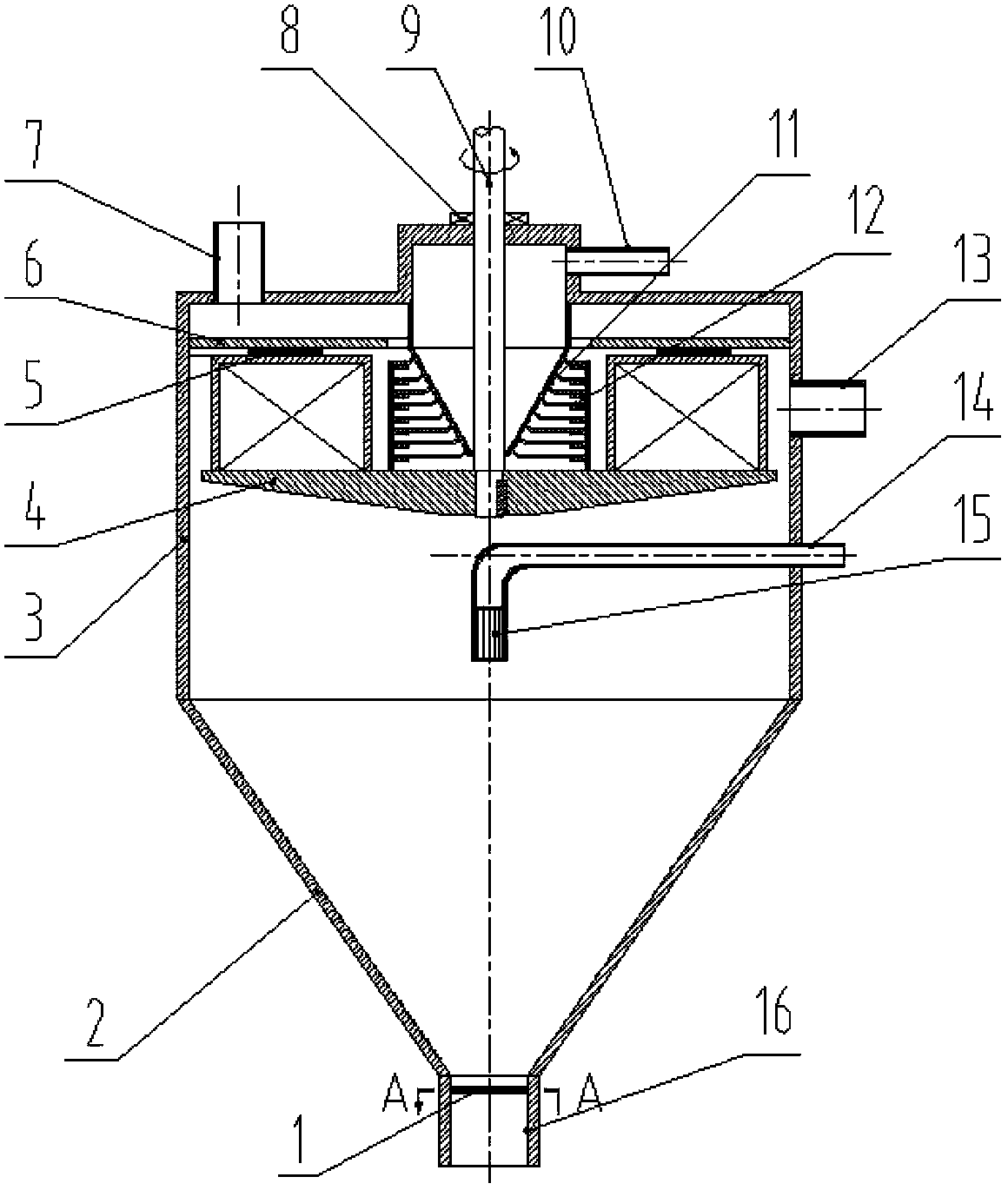
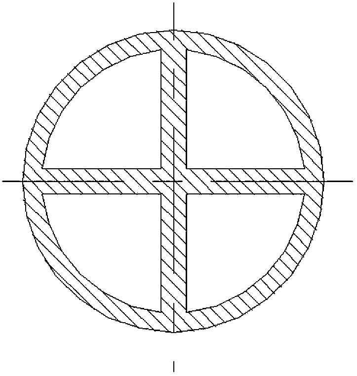
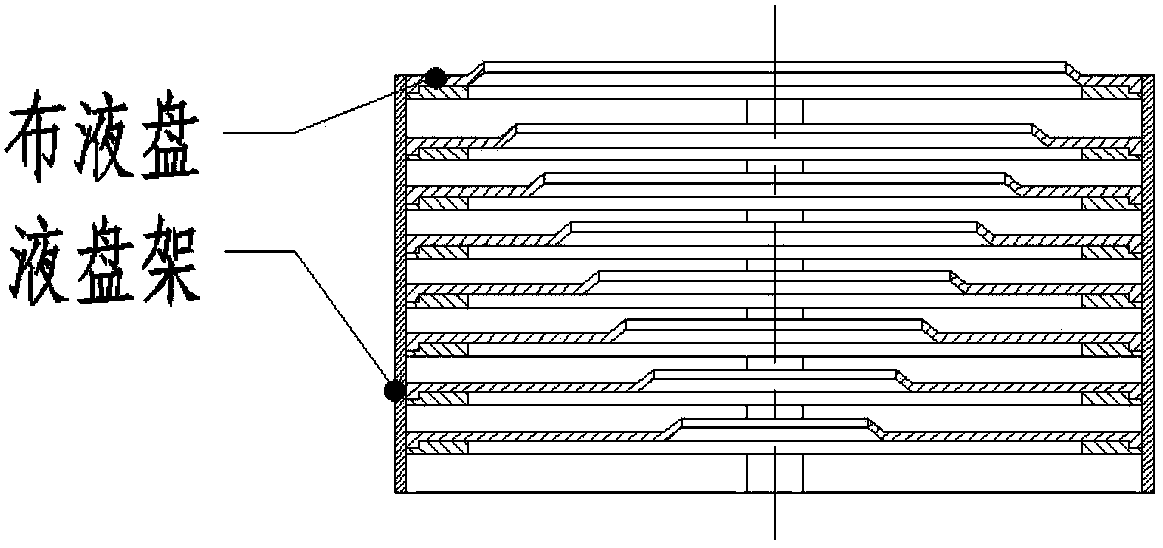
[0039] figure 1A schematic diagram of a supergravity three-phase mass transfer separation rotating bed is schematically shown, which is divided into a supergravity three-phase contact mass transfer section 3 and a lower cyclone solid-liquid separation section 2. The supergravity three-phase mass transfer separation rotary bed It includes: a rotating shaft 9, a mechanical seal 8 is arranged between the rotating shaft 9 and the shell of the supergravity three-phase mass transfer separation rotating bed; a rotor 4, the rotor 4 is arranged on the rotating shaft 9 and is located in the supergravity Within the gravity three-phase contact mass transfer section 3, a labyrinth seal 5 is set between the rotor 4 and the static baffle 6 located inside the shell of the supergravity three-phase mass transfer separation rotating bed; The solid-liquid mixture feed pipe 10 and the gas phase outlet 7 above the shell of the rotating bed for phase transfer and mass transfer separation; the conica...

Embodiment 2

[0046] Figure 5 Another supergravity three-phase mass transfer separation rotary bed is schematically shown, which is exactly the same as the supergravity three-phase mass transfer separation rotary bed in Example 1, the difference is that the light phase outlet 14 is arranged in the cyclone solid-liquid separation. Below the section 2, near the heavy phase outlet 16, so that the separated light and heavy phases flow to the bottom of the shell and flow out from the corresponding outlets respectively. The shell above the heavy phase outlet 16 is designed as a gradually expanding circular truncated structure, which can provide space for the pipeline of the light phase outlet 14 on the one hand, and further reduce the rotation speed of the heavy phase and reduce the pressure drop of the equipment on the other hand.

Embodiment 3

[0048] Image 6 Schematically shows another supergravity three-phase mass transfer separation rotating bed, which is exactly the same as the supergravity three-phase mass transfer separation rotating bed in Example 1, the difference is that the shape of the inner surface of the cyclone solid-liquid separation section It is different from the situation in Example 1. The cyclone solid-liquid separation section 2 is in the form of cone 1-cylinder-cone 2, which is suitable for gas, liquid and solid three-phase supergravity mass transfer separation devices with larger diameters. The existence of the cone 1-shaped line can improve the tangential velocity of the material liquid thrown out from the outer edge of the rotor 4, improve the solid-liquid separation efficiency, increase the liquid volume ratio of the cyclone solid-liquid separation section 2, and reduce the cyclone solid-liquid separation section 2. volume.

[0049] It should be noted that the light phase outlet 14 and th...


PUM


Abstract

The invention relates to a use method of a super-gravity three-phase mass transferring and separating rotary bed, wherein the method comprises steps as follows: providing the super-gravity three-phase mass transferring and separating rotary bed; and using the super-gravity three-phase mass transferring and separating rotary bed for separation. The super-gravity three-phase mass transferring and separating rotary bed is divided into a super-gravity three-phase mass transfer section on the upper part and a whirl solid-liquid separation section on the lower part, and comprises a rotating shaft, a rotor, a conical static material liquid distributor, a rotary liquid distribution disc and a vortex stopping device. A gas phase outlet, a light phase outlet and a heavy phase outlet are formed in a shell of the super-gravity three-phase mass transferring and separating rotary bed. The super-gravity three-phase mass transferring and separating rotary bed has advantages as follows: 1, the mass transfer and the pre-separation or even complete separation of gas, liquid and solid phases are simultaneously realized, and the method is applicable to various unit operation processes such as rectification and absorption; and 2, the static-dynamic liquid distribution method not only simplifies the structure of a liquid inlet and is easy to seal, but also realizes axial and circumferential initial distribution of the liquid.

Description

technical field [0001] The present invention relates to the technical field of supergravity, in particular to a method for using a supergravity three-phase mass transfer separation rotating bed. Background technique [0002] Hypergravity field technology is a breakthrough technology for enhancing transport and multiphase reaction processes. In practical applications, the way to achieve a hypergravity environment is to generate centrifugal force through rotation. This specially designed rotating device is called a hypergravity machine or a hypergravity rotating bed, and is also known as "the chemical industry's first" because of its breakthrough advantages. transistor". However, the function of the supergravity rotating bed device currently used in the industry is limited to the mass transfer and separation of gas phase and liquid phase or solid-liquid mixture, and cannot realize the separation of gas, liquid and solid three phases while enhancing mass transfer. The prior a...

Claims


Application Information

Patent Timeline
Patent Type & Authority Patents(China)
IPC IPC(8): B01D3/30B01D53/18B01J19/18
Inventor 马庆芬卢辉
Owner HAINAN UNIVERSITY
Learn More