Lead disc granulator and design method thereof
A design method and granulator technology, applied in the direction of presses, manufacturing tools, die extrusion granulation, etc., can solve problems such as loss of lead materials, waste of energy, pollution of the environment, etc.
- Summary
- Abstract
- Description
- Claims
- Application Information
AI Technical Summary
Problems solved by technology
Method used
Image
Examples
Embodiment 1
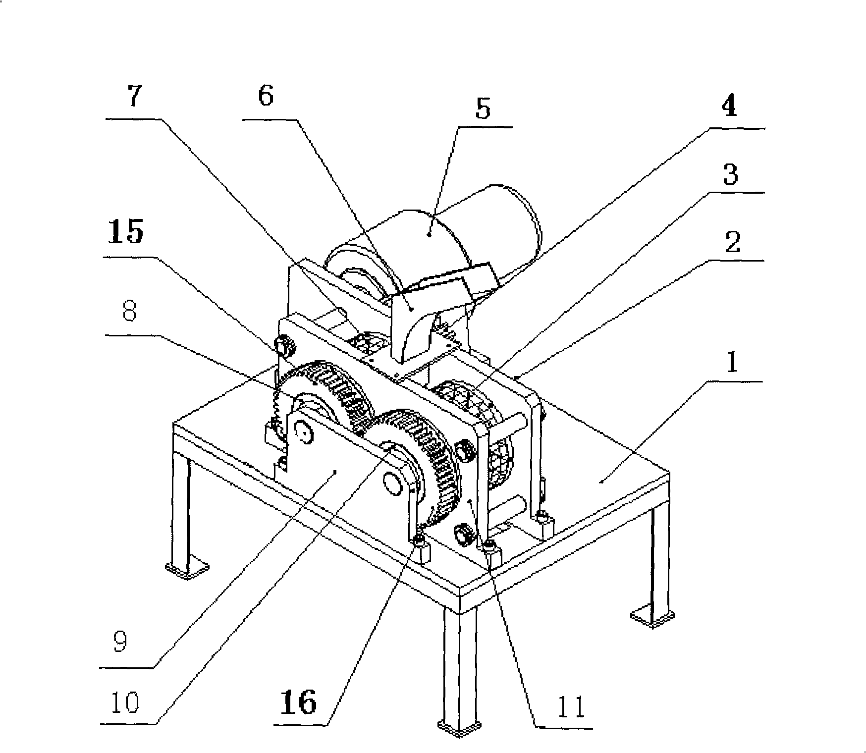
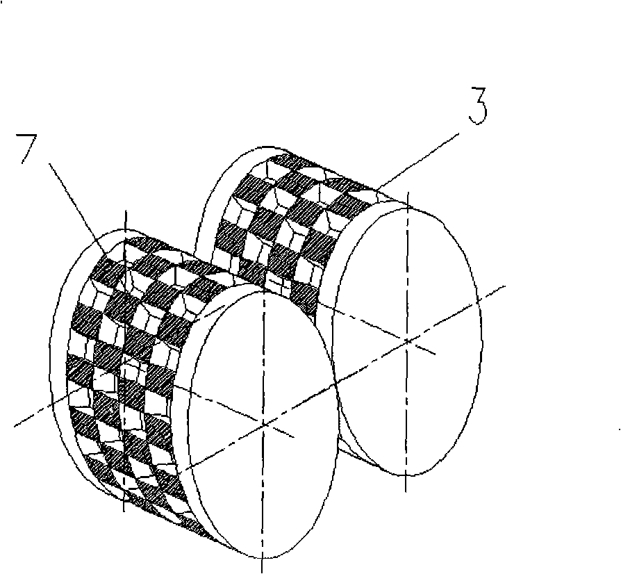
[0018] Example 1 as figure 2 As shown, there are two bosses and two grooves arranged alternately in each row on the peripheral surface of its driving squeeze roller 7 and driven squeeze roller 3 . The boss of the active squeeze roller 7 corresponds to the groove position of the driven squeeze roller 3, to ensure that the boss of the active squeeze roller 7 can be just right when the active squeeze roller 7 and the driven squeeze roller 3 roll against each other synchronously. Align the groove of the driven squeeze roller 3.
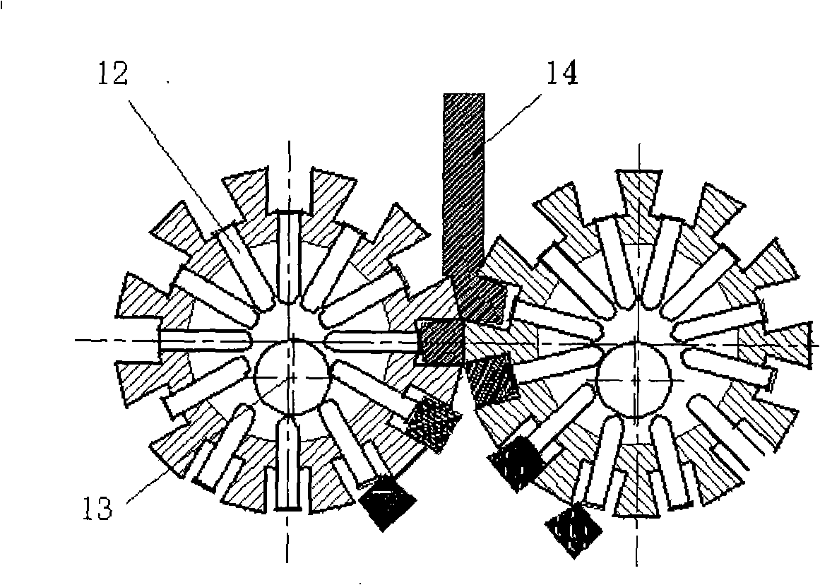
[0019] Example 1 as image 3 As shown, when the lead cake 14 enters the joint between the active extrusion roller 7 and the driven extrusion roller 3, the driven extrusion roller 3 will rotate due to the power mechanism driving the active extrusion roller 7 to rotate through the engagement of the transmission gear 4. Synchronously rotating with the active squeeze roller 7, the lead cake 14 is squeezed into the groove to become lead pellets, and then pu...
Embodiment 2
[0020] Embodiment 2 is basically the same as Embodiment 1, except that the curved surfaces of the two extrusion rollers are distributed with concave and convex staggered bosses and grooves of different sizes, and the bosses and grooves in the middle of the curved surface of the extrusion rollers are The grooves have the same size, but the bosses and grooves on both sides of the curved surface of the extrusion roller are larger than those in the middle, because the lead cake 14 is not completely regular in size, so the two sides of the curved surface of the extrusion roller When the boss and the groove are larger than the boss and the groove in the middle, the leftover material can be fully used, saving raw materials. The difference between embodiment 2 and embodiment 1 is that the ejector mechanism is composed of an eccentric cam and ejector rods; or the ejector rod mechanism is formed by a spring connected to the bottom of each ejector rod. In the present invention, the lead ...
PUM
 Abstract
Description
Claims
Application Information
 - R&D
- Intellectual Property
- Life Sciences
- Materials
- Tech Scout
- Unparalleled Data Quality
- Higher Quality Content
- 60% Fewer Hallucinations
Browse by: Latest US Patents, China's latest patents, Technical Efficacy Thesaurus, Application Domain, Technology Topic, Popular Technical Reports.
© 2025 PatSnap. All rights reserved.Legal|Privacy policy|Modern Slavery Act Transparency Statement|Sitemap|About US| Contact US: help@patsnap.com


