AI technical title is built by Patsnap AI team. It summarizes the technical point description of the patent document.
A radial tire and tire technology, which is applied to the reinforcement layer, tire parts, tire tread/tread pattern of pneumatic tires, etc. Layer bending and other problems, to achieve the effect of maintaining cost competitiveness and improving partial wear performance
Inactive Publication Date: 2012-07-04
BRIDGESTONE CORP
View PDF1 Cites 0 Cited by
Summary
Abstract
Description
Claims
Application Information
AI Technical Summary
This helps you quickly interpret patents by identifying the three key elements:
Problems solved by technology
Method used
Benefits of technology
Problems solved by technology
[0005] However, in tires with a 2-steel belt structure, the belt layer width is narrower than the ground contact width due to manufacturing and durability reasons, so the belt cannot be restricted by the belt layer in the vicinity of the belt end of the shoulder portion. The radial deformation of the ply increases, so it is impossible to avoid the problem that the radial direction of the tire is greatly increased due to the centrifugal force during high-speed driving
There is a problem that if the radially increasing deformation of the shoulder portion is large in this way, a circumference difference will be generated between the shoulder portion and the middle portion, and the shoulder portion with a long circumference will be caused by driving. shoulder wear
[0006] In addition, in the 2-steel belt structure, since there is no belt reinforcement layer such as a cap and a layer, the belt may be bent, and a shoulder area may be formed in the ground contact surface. (shoulder block) Friction drawn inward
Method used
Image
Click on the blue label to locate the original text in one second.
Reading with bidirectional positioning of images and text.
Examples
Embodiment 1
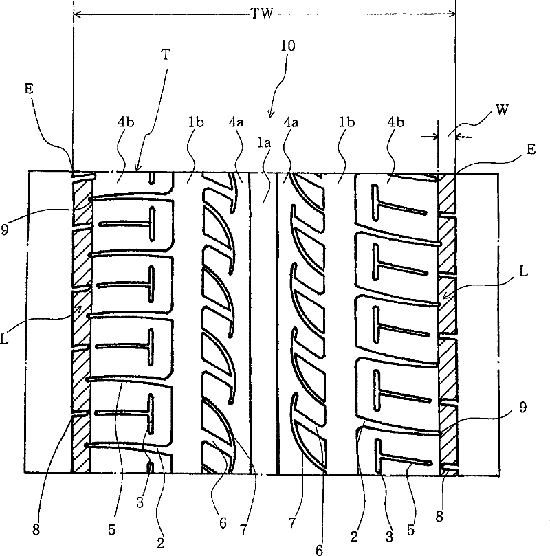
[0039] has been trial-produced with figure 1 A tire with the tread pattern shown and a 2-steel belt structure that satisfies the following conditions.
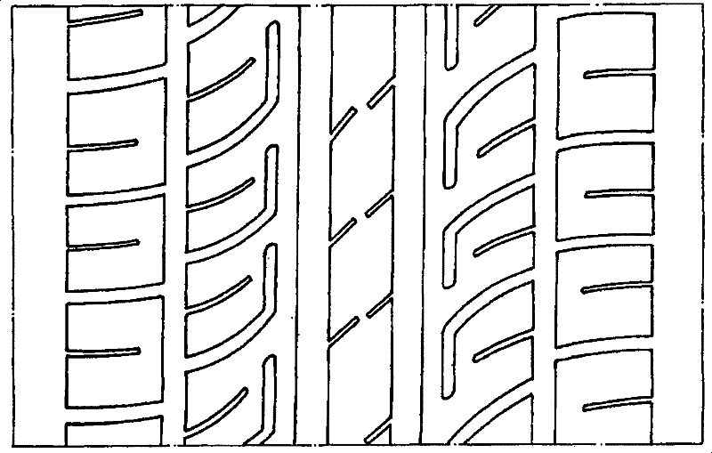
[0053] use has image 3 A known tire having the tread pattern and...
Embodiment 2
[0070] Trial out: In addition to having Figure 4 A tire having one belt reinforcement layer in addition to the tread pattern and two-wire belt structure shown, and satisfying the following conditions.
[0084] Adopted in previous example 2: with Figur...
PUM
Abstract
The invention provides a pneumatic radial tire having cost competition and improving the bias abrasion performance to the tire shoulder by seeking for the optimization of the ground shape and the ground pressure. The pneumatic radial tire has a translot (2) having a plurality of circumferential main slots (1a, 1b) at the tread portion of the tire and extending along the width direction of the tire and a tread pattern for forming a plurality of ground lines (4a, 4b). In the tier shoulder ground line (4b) comprising ground end (E), a translot (2) extending from the circumferential main slots (1b) nearest to the ground end to the ground end (E) is stopped near the ground end, and continuous ground portions (L) are formed near the ground end. Side of the main slots (1b) of the tier shoulder ground line (4b) is approximately parallel to the intermittent slit auxiliary slot (3).
Description
technical field [0001] The present invention relates to a pneumatic radial tire. Specifically, it relates to a pneumatic radial tire which is cost-competitive and which improves partial wear performance of tire shoulders by optimizing the contact shape and contact pressure distribution. Background technique [0002] Conventionally, it is known in pneumatic tires that, for example, as described in Patent Document 1, by arranging a belt reinforcing layer between the belt layer and the tread, it is possible to suppress the centrifugal force during high-speed running from causing the tire to rotate. The tread portion produces a large radially increasing deformation toward the outside in the radial direction, and therefore, it is generally possible to reduce heat generation and deformation at the belt end, improve high-speed durability, and improve steering stability. [0003] However, the following tires are still widely used today because they do not have a belt reinforcement l...
Claims
Application Information
Patent Timeline
Application Date:The date an application was filed.
Publication Date:The date a patent or application was officially published.
First Publication Date:The earliest publication date of a patent with the same application number.
Issue Date:Publication date of the patent grant document.
PCT Entry Date:The Entry date of PCT National Phase.
Estimated Expiry Date:The statutory expiry date of a patent right according to the Patent Law, and it is the longest term of protection that the patent right can achieve without the termination of the patent right due to other reasons(Term extension factor has been taken into account ).
Invalid Date:Actual expiry date is based on effective date or publication date of legal transaction data of invalid patent.

