

Horizontal current aluminium cell
An aluminum electrolytic cell and horizontal current technology, which is applied in the field of electrolytic cell structure, can solve problems such as fluctuations in the aluminum liquid layer, complex busbar structure, and reduced production efficiency of aluminum electrolysis, and achieve long service life, material saving, and good social and economic benefits Effect
Inactive Publication Date: 2008-11-19
HENAN ZHONGFU IND
View PDF0 Cites 14 Cited by
- Summary
- Abstract
- Description
- Claims
- Application Information
AI Technical Summary
Problems solved by technology
The capacity of the electrolytic cell is large, and the structure of the busbars entering and exiting the electrolytic cell is complex, so that there will be magnetic fields in different directions, in which the magnetic field generated by the horizontal current will interact with the magnetic field generated by the vertical current in the aluminum liquid, causing the aluminum liquid layer to fluctuate. Resulting in lower production efficiency of aluminum electrolysis
Method used
View moreImage
Smart ImageViewing Examples

Examples
Embodiment
Login to View More PUM
 Abstract
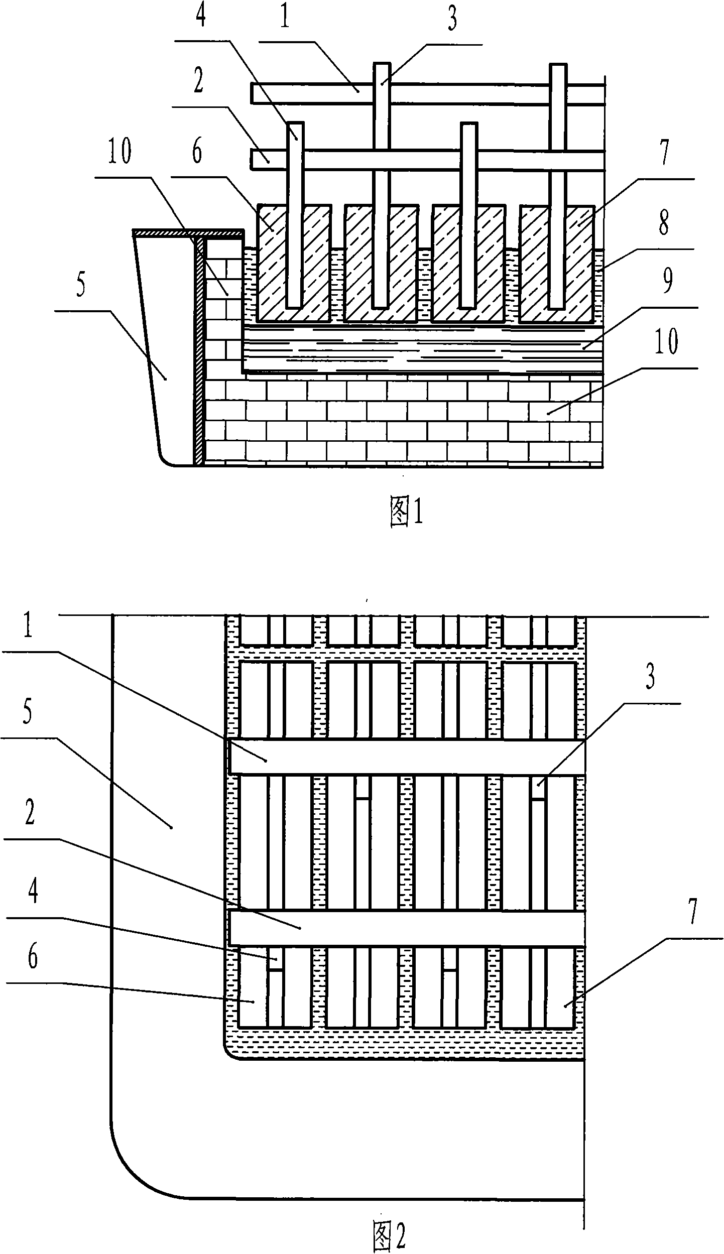
The invention discloses a horizontal current aluminum electrolytic bath. The aluminum electrolytic bath comprises a melting bath part and an electrode part, wherein the melting bath part consists of a steel bath shell(5) and fire proof and heat proof materials(10); the upper end of the bath shell(5) adopts an open type structure; while the electrode part consists of a cathode electrode part and an anode electrode part, wherein the cathode electrode part consists of a cathode electrode(6), a cathode electrically conductive pole(4) and a cathode bus(2) applied to discharge electric current, and the anode electrode part consists of an anode electrode(7), an anode electrically conductive pole(3) and an anode bus(1) applied to charge electric current; the electrode part are hanged in the bath shell(5) by a support steel beam, and a liquid electrolyte layer (8) is arranged between the cathode electrode(6) and the anode electrode(7); electrolytic currents horizontally enter the corresponding side face of the cathode electrode(6) from the side face of the anode electrode(7). The aluminum electrolytic bath has the advantages that the design is novel, no electric current pass through the melting bath, no electrochemical reaction happens, the aluminum electrolytic bath does not need to be drilled around, along with long service life and good social and economic benefits.
Description
Horizontal current aluminum electrolytic cell Technical field: The invention relates to an aluminum electrolytic cell, in particular to a horizontal current aluminum electrolytic cell, which belongs to the field of electrolytic cell structures. Background technique: At present, the direction of the electrolytic current in the electrolytic cell used in the production of electrolytic aluminum industry is vertical, that is, the current flows from the anode at the upper part of the electrolytic cell vertically to the cathode at the bottom. The problems that exist in this way are: 1. A strong current of hundreds of thousands of amperes flows through the bottom of the molten pool of the electrolytic tank. Under the action of electrochemical reaction, the carbon cathode at the bottom expands and breaks, which keeps the life of the electrolytic tank at about 1800 days. 2. The electrolytic cell passes through a strong current of hundreds of thousands of amperes, which will gener...
Claims
Login to View More Application Information
Patent Timeline
 Patent Type & AuthorityApplications(China)
IPC IPC(8): C25C3/08
Inventor梁学民王有山
OwnerHENAN ZHONGFU IND