Hydraulic automobile transmission differential mechanism

A differential mechanism and automobile technology, applied in the direction of liquid fuel engines, transmissions, differential transmissions, etc., can solve the problems of unfavorable automobile miniaturization, complex structure, and large volume

Inactive Publication Date: 2008-11-19
冯政民
View PDF0 Cites 4 Cited by
  • Summary
  • Abstract
  • Description
  • Claims
  • Application Information

AI Technical Summary

Problems solved by technology

[0002] In the existing automobile field, the work done by the automobile engine is sequentially transmitted to the wheels through the clutch, transmission, transmission shaft, differential, and then through the half shaft. This structure is large in size and complex in structure, which is not conducive to miniaturization of cars
Among them, the differential is designed to prevent the outer wheel from slipping while rolling and the inner wheel from slipping due to the outer wheel moving a greater distance than the inner wheel when the car is turning. Yes, it is usually achieved through a large number of gears, and the structure is very complicated

Method used


Image

  • Hydraulic automobile transmission differential mechanism
  • Hydraulic automobile transmission differential mechanism
  • Hydraulic automobile transmission differential mechanism

Examples


Embodiment Construction

[0022] The present invention will be further described below in conjunction with the accompanying drawings and embodiments.

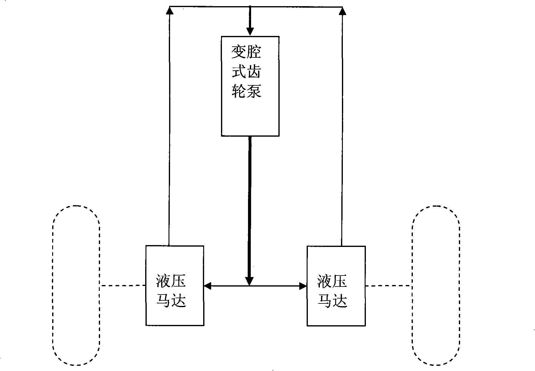
[0023] Such as figure 1 As shown, the hydraulic vehicle transmission and the differential mechanism of the present invention comprise a variable chamber gear pump and two hydraulic motors connected with the half shaft, wherein the liquid outlet of the variable chamber gear pump is connected to the two hydraulic motors The liquid inlets are connected through pipelines, and the liquid outlets of the two hydraulic motors are connected with the liquid inlets of the variable cavity gear pump through pipelines to form two driving oil circuits.

[0024] Among them, the above-mentioned variable cavity gear pump has the characteristics of stepless output power without the need for relief valves or other pressure limiting valves; through the variable cavity gear pump, the power output by the engine can be driven through the pipeline to drive the hydraulic motor t...


PUM


Abstract

The invention discloses a hydraulic automobile transmission-differential mechanism, which is invented for solving large volume, complex structure and other problems of the prior art. The mechanism comprises a variable cavity type gear pump and two hydraulic motors connected with a half shaft, wherein a liquid outlet of the variable cavity type gear pump is communicated with liquid inlets of the two hydraulic motors through pipelines; liquid outlets of the two hydraulic motors are communicated with a liquid inlet of the variable cavity type gear pump through the pipelines, so as to form two driving oil lines. After the structure is adopted, by utilizing the characteristic of the variable cavity type gear pump in stepless power output, power output by an engine can drive the hydraulic motors to output power through the pipelines so as to drive an automobile to move; moreover, due to hydraulic transmission, the prior automobile differential can be realized by controlling the oil lines. The mechanism is simple in overall structure and can greatly reduce automobile-body space.

Description

technical field [0001] The invention relates to an automobile transmission and differential speed structure. Background technique [0002] In the existing automobile field, the work done by the automobile engine is sequentially transmitted to the wheels through the clutch, transmission, transmission shaft, differential, and then through the half shaft. This structure is large in size and complex in structure, which is not conducive to Miniaturization of automobiles. Among them, the differential is designed to prevent the outer wheel from slipping while rolling and the inner wheel from slipping due to the outer wheel moving a greater distance than the inner wheel when the car is turning. Yes, it is usually realized through a large number of gears, and the structure is very complicated. Contents of the invention [0003] In order to overcome the above-mentioned defects, the object of the present invention is to provide a hydraulic vehicle transmission and differential mech...

Claims


Application Information

Patent Timeline
Patent Type & Authority Applications(China)
IPC IPC(8): F16H39/02F16H48/18F16H48/26F04C2/08
Inventor 冯政民
Owner 冯政民
Why Eureka
Try Eureka