
Patsnap Eureka
For R&D, Patsnap Eureka makes reading and utilizing patents & technical documents easy.
Patsnap Eureka AIR
Designed for self-driven R&D workflows. Generate viable solutions, solve complex R&D challenges, empower your innovation with AI.

Patsnap Eureka Materials
Designed for material experts only. Revolutionize your material R&D, from search, analyze, to developing new materials.

TechResearch
Generate reliable direction feasibility study reports for your R&D in just a few steps.

TechSeek
Discover and master advanced knowledge NOW. Basics, ideas, possibilities, all at once.

TechMind
As an expert in R&D Theories, TechMind can generates customized viable solutions instantly.

TechRisk
Analyze your overall solution with one click, know your potential R&D risks in advance.

TechMonitor
Get weekly tech updates, stay abreast of the latest tech innovations and key insights.
Three-way ball valve
A three-way ball valve and valve body technology, applied in the field of machinery, can solve problems such as single function and difficult to achieve, and achieve the effect of simple structure and low cost
- Summary
- Abstract
- Description
- Claims
- Application Information
AI Technical Summary
Problems solved by technology
Method used
Image

Examples
Embodiment Construction
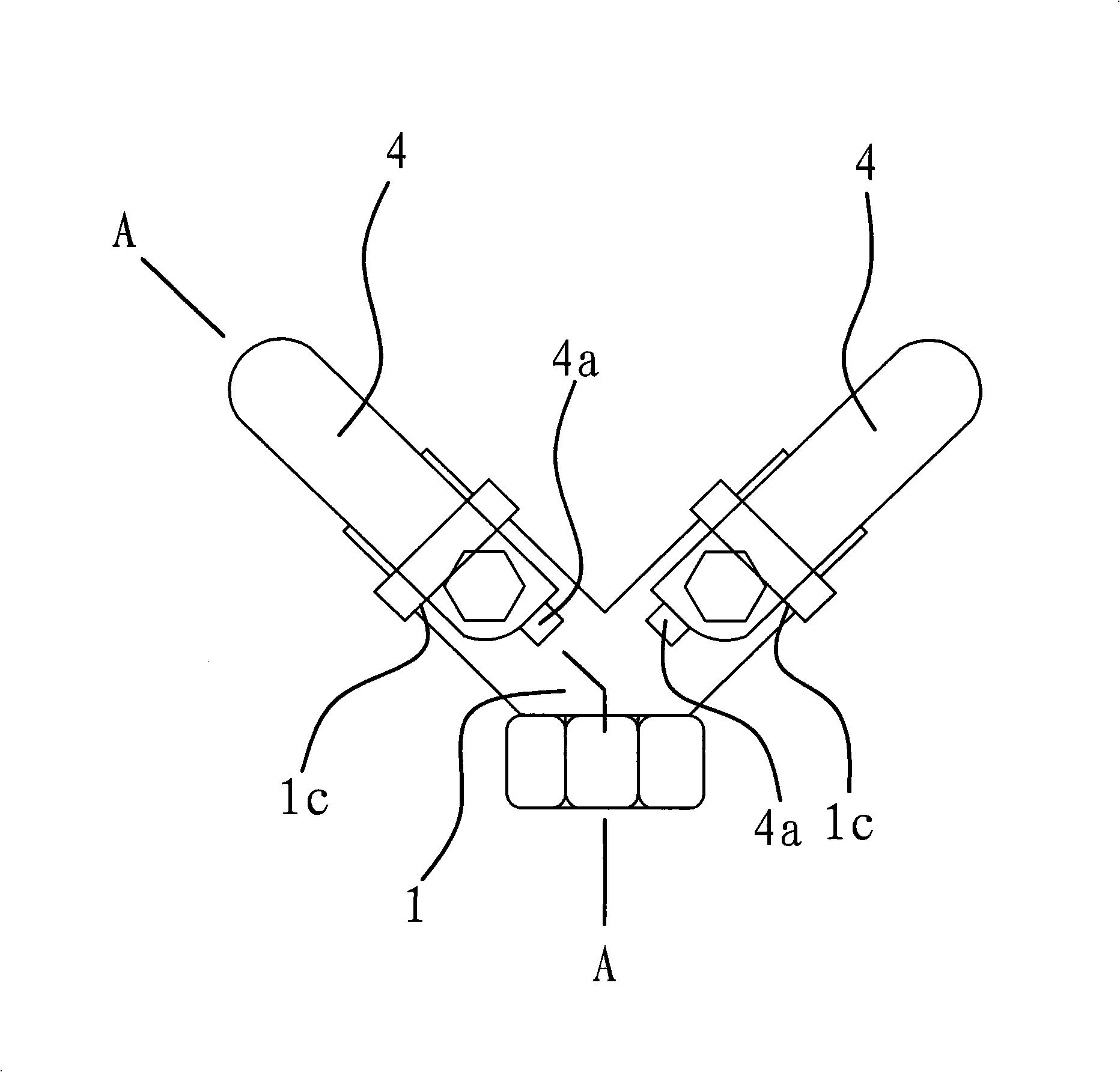
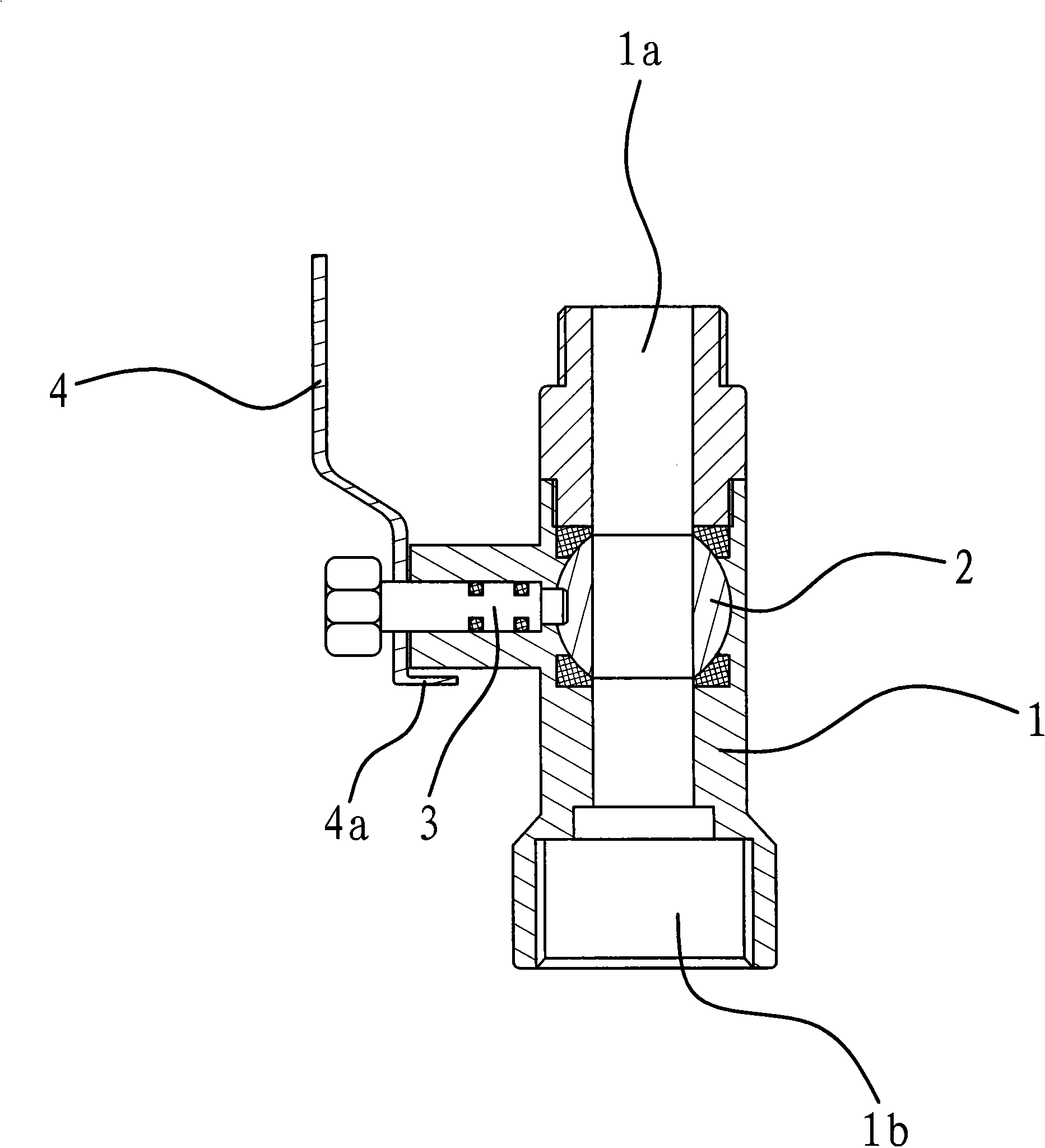
[0021] As shown in Figure 1, the three-way ball valve includes a valve body 1, a valve core 2, a valve stem 3 and a handle 4. The interior of the valve body 1 is a cavity, that is to say, the valve body 1 has two water inlet channels 1a and A water outlet channel 1b.
[0022] The two water inlet channels 1a form an L shape, and the inlet end of the water outlet channel 1b communicates with the corners of the L shape of the two water inlet channels 1a.
[0023] As shown in FIG. 1 and FIG. 2 , there are two valve cores 2 , valve stems 3 and handles 4 . One of the valve cores 2 is installed in one of the water inlet channels 1a, the inner end of the valve stem 3 is fixedly connected with the valve core 2, the outer end of the valve stem 3 passes through the valve body 1, and the handle 4 is fixedly connected with the valve stem 3 outer end. The other valve core 2 is installed in another water inlet channel 1a, and the valve stem 3 and the handle 4 are connected in the same way,...
PUM
 Abstract
Description
Claims
Application Information
 - R&D Engineer
- R&D Manager
- IP Professional
- Industry Leading Data Capabilities
- Powerful AI technology
- Patent DNA Extraction
Browse by: Latest US Patents, China's latest patents, Technical Efficacy Thesaurus, Application Domain, Technology Topic, Popular Technical Reports.
© 2024 PatSnap. All rights reserved.Legal|Privacy policy|Modern Slavery Act Transparency Statement|Sitemap|About US| Contact US: help@patsnap.com