Flat-plate evaporators structure and loop type hot pipe possessing flat-plate evaporators structure

An evaporator and flat plate technology, applied in the field of loop heat pipes, can solve the problems of water molecules overflowing and unable to meet the heat dissipation requirements of microelectronic components, and achieve the effects of rapid response, avoiding short circuit of electronic components, and small thermal resistance

Inactive Publication Date: 2008-11-19
TAMKANG UNIVERSITY
View PDF0 Cites 41 Cited by
  • Summary
  • Abstract
  • Description
  • Claims
  • Application Information

AI Technical Summary

Problems solved by technology

The existing heat dissipation fin-fan-based heat dissipation mechanism is bound to be unable to meet the heat dissipation needs of future microelectronic components. Moreover,

Method used


Image

  • Flat-plate evaporators structure and loop type hot pipe possessing flat-plate evaporators structure
  • Flat-plate evaporators structure and loop type hot pipe possessing flat-plate evaporators structure
  • Flat-plate evaporators structure and loop type hot pipe possessing flat-plate evaporators structure

Examples


Embodiment Construction

[0053] The specific embodiments adopted by the present invention will be further described through the following embodiments and accompanying drawings.

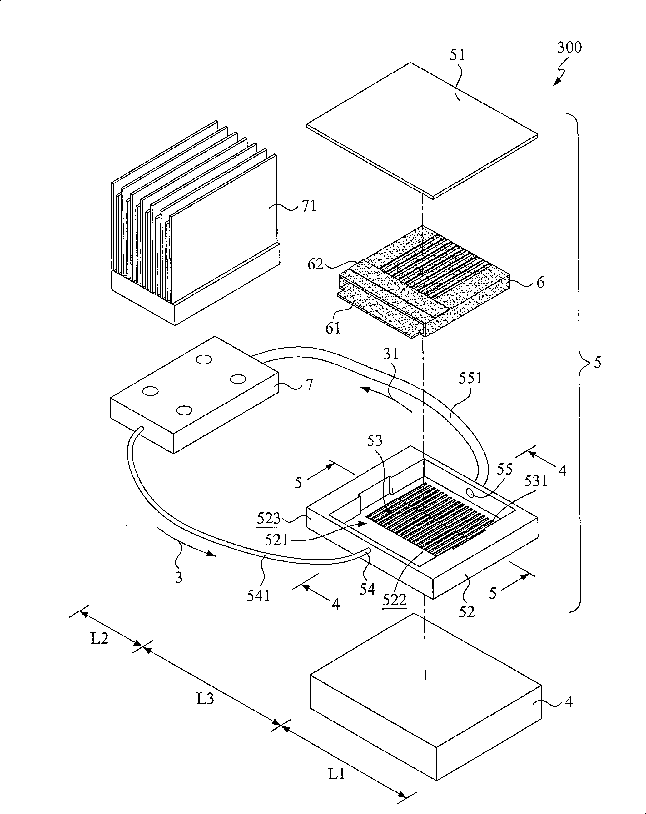
[0054] refer to image 3 As shown, it is a perspective view showing the loop heat pipe of the present invention with a flat plate evaporator structure, Figure 4 for display image 3 The 4-4 cross-sectional view, Figure 5 for display image 3 The 5-5 cross-sectional view. The evaporator 300 of the present invention is composed of an evaporating section L1 disposed on a heat source 4, and a conducting section L3 connected to a condensing section L2.

[0055] The evaporation section L1 includes an airtight accommodation structure 5 arranged on the heat source 4. The airtight accommodation structure 5 is composed of a cover body 51 and a box body 52 to form an airtight accommodation space 521, and includes There is a capillary structure 6 , a liquid inlet 54 and a corresponding gas outlet 55 .

[0056] The capillary struc...


PUM


Abstract

The invention discloses a flat evaporator structure and a loop heat pipe with the flat evaporator structure, the loop heat pipe has an evaporation section arranged on a heat source and a conduction section connected with a condensation section, the evaporation section includes an enclosed containment structure and a capillary structure, and has a bottom in which a channel structure is formed, and a liquid inlet and a gas outlet are arranged in a lateral margin of a container body to respectively connect a gas passage and a liquid passage, so that when a working fluid is heated by the heat source to become vapor, the vapor moves through the gas outlet and the gas passage to a condensing device in the condensation section where the vapor is cooled and converted back to the original form of the working fluid that is then guided through the liquid passage back to the enclosed containment structure for next cycle.

Description

technical field [0001] The invention relates to a loop heat pipe, in particular to a loop heat pipe with a flat plate evaporator structure. Background technique [0002] Due to the progress of the semiconductor process, the number of wires on the chip has been increasing. In order to accommodate these wires, the area after packaging is often several times the die area. Therefore, the heat on the surface of the package is not evenly distributed, and it is easy to form hot spots (Hotspot) and then cause chip damage due to uneven thermal stress. The role of the heat pipe is to quickly guide the heat to other heat sinks, and then remove the heat through the heat dissipation module. The current heat pipe design is mostly used in the heat dissipation of notebook computers, including the following methods: [0003] (1) Forced air cooling; [0004] (2) Forced liquid cooling; [0005] (3) heat pipe phase change heat dissipation; [0006] (4) Refrigerator heat dissipation; [000...

Claims


Application Information

Patent Timeline
IPC IPC(8): F28D15/02F28D15/04H05K7/20H01L23/427
CPCF28D15/0266H01L2924/0002
Inventor 康尚文蔡孟昌
Owner TAMKANG UNIVERSITY
Why Eureka
Try Eureka