Optical inspection device

A technology of optical inspection and irradiation of light, applied in the direction of using optical devices, measuring devices, optical radiation measurement, etc., can solve the problems of difficult inspection and reduced productivity, and achieve the effect of high-quality inspection

Inactive Publication Date: 2008-11-19
AJUHITEK
View PDF0 Cites 12 Cited by
  • Summary
  • Abstract
  • Description
  • Claims
  • Application Information

AI Technical Summary

Problems solved by technology

Therefore, as the line width becomes smaller, it gradually becomes difficult to inspect with the naked eye, resulting in a decrease in productivity. In order to solve this problem, it is necessary to introduce an optical automatic inspection system

Method used


Image

  • Optical inspection device
  • Optical inspection device
  • Optical inspection device

Examples


no. 1 approach

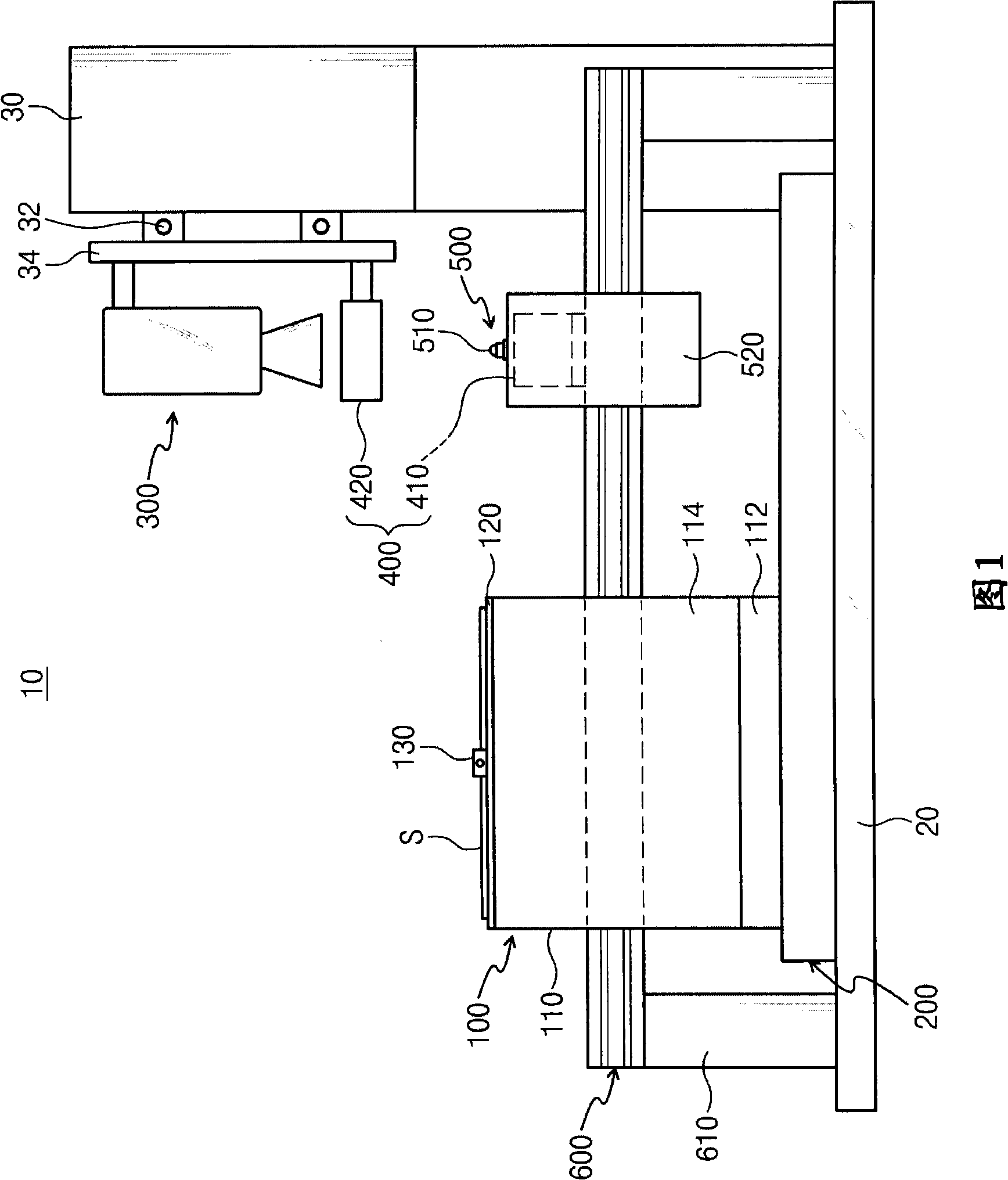
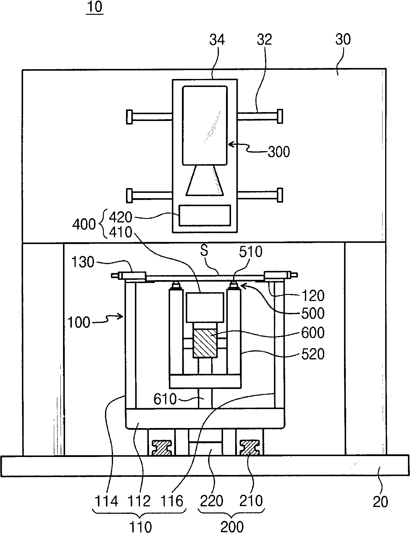
[0042] FIG. 1 is a front view illustrating the structure of an optical inspection device according to a first embodiment of the present invention, figure 2 It is a side view illustrating the structure of the optical inspection device according to the first embodiment of the present invention.

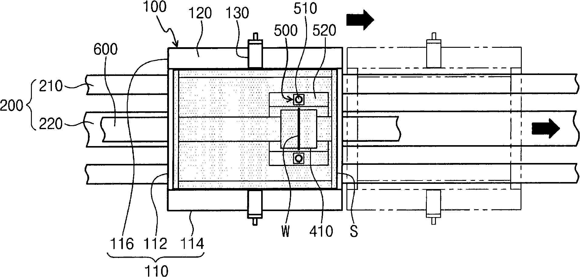
[0043] Referring to Figure 1 and figure 2 , the optical inspection device 10 of the present invention includes a stage 100 , a linear movement unit 200 , an imaging unit 300 , an illumination unit 400 and a rolling member 500 .

[0044] Stage

[0045] The stage 100 includes a body 110 having a bottom surface 112 , a first side 114 and a second side 116 . On the upper layer of the fuselage 110 , that is, on the upper layer of the first side 114 and the second side 116 , a bracket 120 and a positioning member 130 are provided. The inspection object S is placed in a state where both side edges are supported on the stand 120 . The positioning member 130 is a cylindrical body for posit...

no. 2 approach

[0060] 5 is a front view for explaining the structure of an optical inspection device according to a second embodiment of the present invention, Figure 6 It is a side view for explaining the structure of the optical inspection apparatus of 2nd Embodiment of this invention.

[0061] Unlike the first embodiment in which the imaging unit, the lighting unit, and the rolling member are fixed, and only the stage is moved to inspect the inspection object, in the second embodiment, the imaging unit and the lighting unit are fixed. The rolling member moves together with the stage, and the inspection object is inspected simultaneously.

[0062] Referring to Figure 5 and Figure 6 , The optical inspection device 10a of the present invention includes a stage 100a, a linear movement unit 200a, a photographing unit 300a, an illumination unit 400a, a rolling member 500a, and the like.

[0063] The stage 100a includes a body 110 having a bottom 112 , a first side 114 and a second side 116 ...


PUM


Abstract

The invention provides an optical check device capable of preventing distortion caused by bending, nutation etc. of the checking objects. The optical check device of the invention comprises: an object state for placing the checking object; an imaging unit for imaging the checking object placed on the object state; a light unit for lightening the checking object; and a rolling component for supporting the edge of the area imaging by the imaging unit and keeping flatness of the imaging area.

Description

technical field [0001] The present invention relates to an optical inspection device for a printed circuit board, and in particular to inspecting a pattern formed on an inspection object (printed circuit board) by photographing the pattern (pattern) formed on the inspection object (printed circuit board) and processing the photographed image information There is an optical inspection device for defects. Background technique [0002] Various printed circuit boards are rapidly changing from existing rigid printed circuit boards to flexible printed circuit boards, and in accordance with the recent needs of light, thin, and small electronic products, the line width of the circuit board is further reduced so that it can be applied to a variety of form of product. Therefore, as the line width becomes smaller, it becomes increasingly difficult to inspect with the naked eye, resulting in a decrease in productivity. In order to solve this problem, it is necessary to introduce an opt...

Claims


Application Information

Patent Timeline
Patent Type & Authority Applications(China)
IPC IPC(8): G01N21/956G01R31/309G01B11/00
CPCG01J1/0223G01N21/956G06T7/0008H05K13/08
Inventor 崔铉镐金敏秀
Owner AJUHITEK
Why Eureka
Try Eureka