Common frequency multi-mode multi-stage whirling traveling-wave tube amplifier
A traveling wave tube amplifier and different-mode technology, which is applied in the field of high-power millimeter-wave sources, can solve the problems that the phase cannot be locked and cannot be applied, and achieve the effect of increasing the power of the device
Inactive Publication Date: 2008-11-19
UNIV OF ELECTRONIC SCI & TECH OF CHINA
View PDF0 Cites 10 Cited by
- Summary
- Abstract
- Description
- Claims
- Application Information
AI Technical Summary
Problems solved by technology
The disadvantage is that the frequency multiplication method is completely nonlinear, and the phase cannot be locked, so it cannot be applied to some communication applications
Method used
View moreImage
Smart ImageViewing Examples
Examples
Embodiment
Login to View More PUM
 Abstract
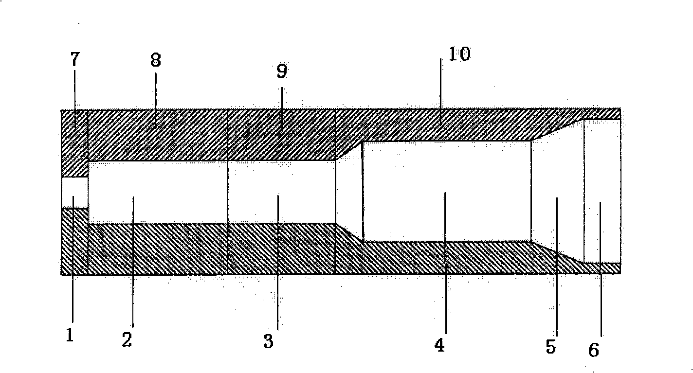
The invention discloses a multi-stage gyro-traveling-wave tube amplifier which works with different modes on waves with the same frequency. The multi-stage gyro-traveling-wave tube amplifier is characterized in that the amplifier is composed of an electron stream passage(1), an input segment(2), a cut-off segment(3), an output segment(4), an output varying waveguide(5), and an output even waveguide(6). The electron stream passage(1) is connected with the input segment(2) which is in connection with the cut-off segment(3); the cut-off segment(3) is connected with the output segment(4) which is connected with the output varying waveguide(5), and the output varying waveguide(5) is connected with the output even waveguide(6). The input segment and the output segment work at the same harmonic wave and the same frequency; the angular indexes of the work modes of the waveguides of the input segment and the output segment are the same; the input segment works on low level waveguide mode and the output segment works on waveguide mode higher than that of the input segment.
Description
Same-frequency and different-mode multistage gyro-traveling-wave tube amplifier technical field The invention relates to a multistage convoluted traveling wave tube amplifier with the same frequency and different modes, belonging to the technical field of high-power millimeter wave sources. Background technique High-power millimeter-wave radar has very important application prospects in national defense fields such as high-resolution radar imaging, anti-stealth, anti-low-altitude flying targets, anti-sea-skimming missiles, missile defense, and electronic countermeasures. Civilian fields such as high-energy physics also have good application prospects. To develop high-power millimeter-wave radar, it is necessary to develop a high-power millimeter-wave source first. Traditional vacuum electronic devices have encountered great difficulties in the millimeter-wave frequency band. 而回旋管(1.TwissR.Q.,RobertsJ.A.Electromagneticradiationfrom electronsrotatinginanionizedmediumunderthe...
Claims
Login to View More Application Information
Patent Timeline
 IPC IPC(8): H01J25/00H01J25/34
Inventor 黄勇李宏福
Owner UNIV OF ELECTRONIC SCI & TECH OF CHINA
Features
- R&D
- Intellectual Property
- Life Sciences
- Materials
- Tech Scout
- Unparalleled Data Quality
- Higher Quality Content
- 60% Fewer Hallucinations
Learn More Browse by: Latest US Patents, China's latest patents, Technical Efficacy Thesaurus, Application Domain, Technology Topic, Popular Technical Reports.
© 2025 PatSnap. All rights reserved.Legal|Privacy policy|Modern Slavery Act Transparency Statement|Sitemap|About US| Contact US: help@patsnap.com


