Three-phase controllable silicon phase shift trigger pulse control circuit

A phase-shift trigger and pulse control technology, which is applied to electrical components, output power conversion devices, AC power input to DC power output, etc., can solve the problems of rectification control, difficult procurement, high price, etc., to prevent power-on shock , Strong anti-interference ability, the effect of preventing electric shock

A phase-shift trigger and pulse control technology, which is applied to electrical components, output power conversion devices, AC power input to DC power output, etc., can solve the problems of rectification control, difficult procurement, high price, etc., to prevent power-on shock , Strong anti-interference ability, the effect of preventing electric shock

CN101309044AActive Publication Date: 2008-11-19CHINA RAILWAY NO 5 ENG GRP

Image

  • Three-phase controllable silicon phase shift trigger pulse control circuit
  • Three-phase controllable silicon phase shift trigger pulse control circuit
  • Three-phase controllable silicon phase shift trigger pulse control circuit

Examples


Embodiment

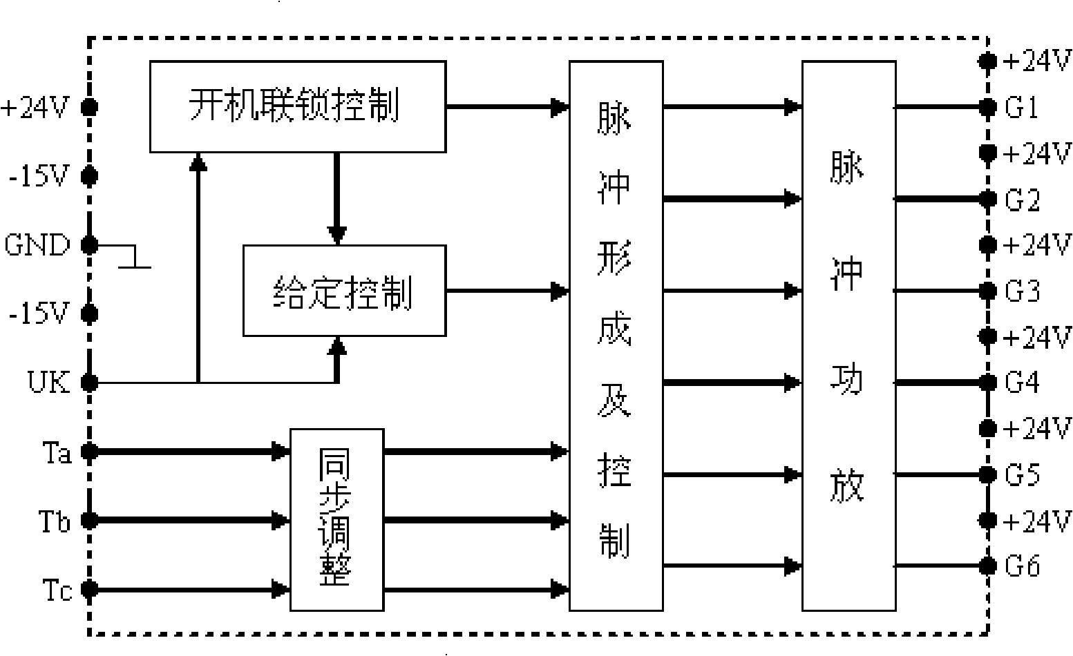
[0038] Embodiment: The given control module 1 is connected with the start-up interlock control module 2 and the pulse shaping and control module 4, and the external given potential is set to a stable phase-shift control voltage, and the working indicator is driven to output the unlocking after the start-up interlock Signal.

[0039] The start-up interlocking control module 2 is connected with the given control module 1 and the pulse shaping and control module 4, so that the system can work in the zero position state after being powered on abnormally.

[0040] The synchronous adjustment module 3 is connected with the pulse shaping and control module 4 to keep the synchronous signal consistent with the phase in the main circuit.

[0041] The pulse shaping and control module 4 is connected with the given control module 1, the start-up chain control module 2, the synchronous adjustment module 3 and the pulse power amplification module 5, and its function is to output the synchrono...


PUM


Abstract

The invention discloses a three-phase thyristor phase-shift trigger pulse control circuit which is in modularity design. The circuit includes a given control module (1), a startup linkage control module (2), a synchronizing adjusting module (3), a pulse shaping and control module (4) and a pulse power amplifying module (5). The three-phase thyristor phase-shift trigger pulse control circuit of the invention replaces the original old circuit to realize the purpose that the control is much safe, the point impact can be avoided at any situation, the circuit is much simple, the part is easy to purchase and the service life is much long.

Description

technical field [0001] The invention relates to a three-phase controllable circuit, in particular to a three-phase thyristor phase-shift trigger pulse control circuit. Background technique [0002] Railway track laying machines and bridge erecting machines are the main construction machinery of construction enterprises on railway lines. The driving of their carts adopts AC and DC transmission, which is quite different from the AC and DC transmission used by railway diesel locomotives in terms of control methods; The diesel locomotive achieves the purpose of controlling the output power by controlling the speed of the diesel engine, controlling the speed of the generator, controlling the output voltage, and controlling the current output to the traction motor. The AC / DC rectifier circuit of this structure only needs an ordinary three-phase diode rectifier circuit. The generator set of the railway track laying machine bridge erecting machine, in addition to providing power fo...

Claims


Application Information

Patent Timeline
19 Nov 2008
Publication
CN101309044A
IPC
H02M1/06; H02M1/08; H02M7/155
Inventors
ε‡ŒεΈ†; 桦青松