Gliding resistant foundation structure

A basic structure, anti-slip technology, applied in the field of building infrastructure, can solve problems such as increased self-weight, concrete waste, fracture, etc., to increase the anti-slip capability, economical and reasonable design, and increase reliability.

Inactive Publication Date: 2008-11-26
GUIYANG AL-MG DESIGN & RES INST
View PDF0 Cites 0 Cited by
  • Summary
  • Abstract
  • Description
  • Claims
  • Application Information

AI Technical Summary

Problems solved by technology

The traditional foundation mechanism is to increase the self-weight of the foundation to increase the value of Gμ, but the increase in self-weight has caused a lot of waste of concrete; for the foundation structure with an anti-slip toe, as shown in Figure 5, the soil on the bottom surface of the foundation will be The anti-slip toe produces a force that is opposite to the horizontal thrust of the base top, that is, P, and the resultant force of the horizontal thrust becomes (E at -P), obviously, after the denominator horizontal thrust is reduced, the anti-sliding ability of the foundation has been significantly improved, but since the anti-sliding toe is still made of concrete, its joint with the concrete bottom is not firm, It is easy to crack or even break, thereby reducing the anti-slip ability of the foundation

Method used


Image

  • Gliding resistant foundation structure
  • Gliding resistant foundation structure
  • Gliding resistant foundation structure

Examples


Embodiment 1

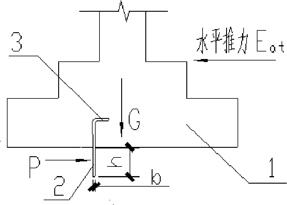
[0023] Embodiment 1, as shown in FIG. 1 , the anti-skid toe 2 is made of steel plate, its upper part goes deep into the foundation base 1 , and its lower part goes deep into the foundation of the foundation. In order to increase the anti-slip capability, there is a bending section 3 at the top of the sliding toe 2 . The steel plate thickness b and height h of the anti-skid toe of the steel plate are determined through design calculations, and their values ​​should be able to meet the shear and bending resistance at the interface between the resistance and the base. After meeting the design requirements, the height h of the anti-skid toe 2 deep into the foundation is 250-450 mm, the height of the upper part deep into the foundation base 1 is the same as the height of the bottom deep into the foundation, and the value of the steel plate thickness b The range should satisfy 0.02h~0.03h, and its length should be set along the general length of the foundation.

Embodiment 2

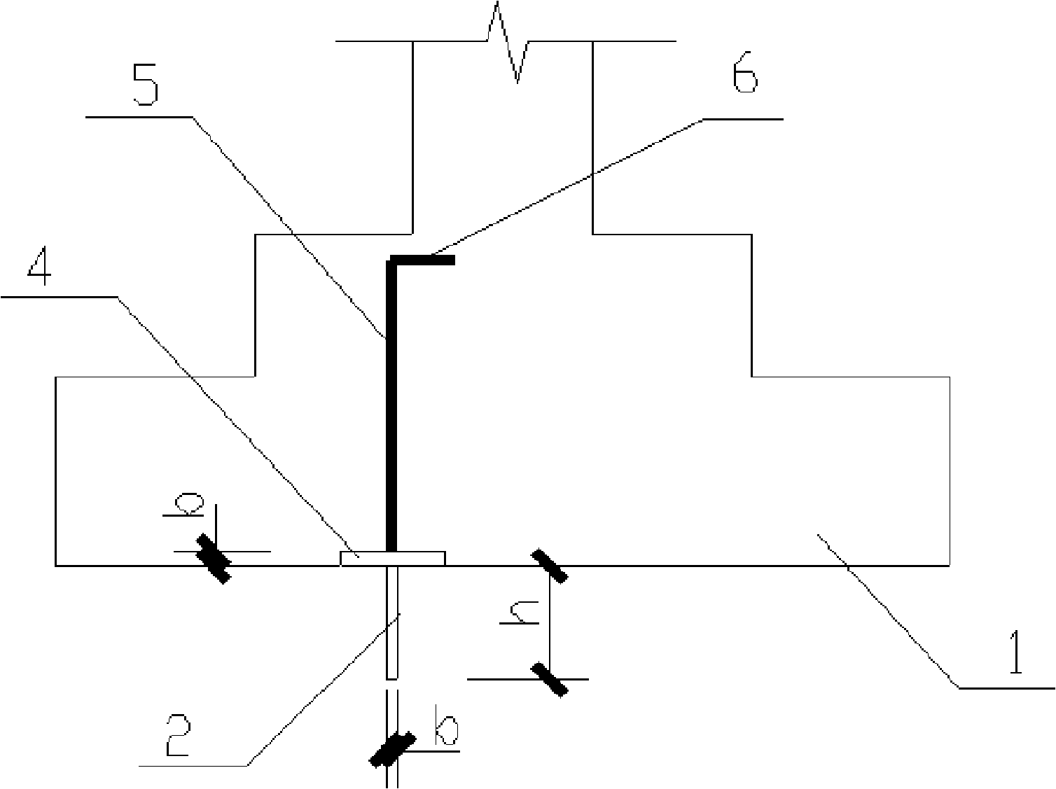
[0024] Embodiment two, as shown in Figure 3, steel plate 4 is set on the top of anti-skid toe 2, adopts " T font fillet weld to connect, and on steel plate 4 welding anchor pulls steel bar 5, anti-skid toe 2, steel plate 4, Anchor the steel bar 5 to form a member, place it in the excavated foundation pit, and then pour the foundation concrete. In order to ensure that the position of the anti-slip toe does not shift during construction, the The anchor bar can be spot-welded with the base plate steel bar for positioning. The steel plate 4 width value is 100mm, and its length value is slightly smaller than the foundation ground width value. In order to increase the anti-sliding ability, there is a bending section at the top of the anchor bar 5 6. The steel plate thickness b and height h of the anti-skid toe of the steel plate are determined through design calculations, and its requirements are the same as those in Embodiment 1. The diameter d of the anchoring steel bar is 8-10mm, ...


PUM


Abstract

The invention discloses an anti-sliding foundation structure. An anti-sliding toe (2) is made of armor plate; the upper part of the anti-sliding toe penetrates deeply into a foundation base (1), and the lower part is inserted in the foundation of the base. In order to fixedly combine the anti-sliding toe with the foundation base, the upper part of the anti-sliding toe (2) is provided with a bent segment (3). In order to improve the anti-sliding ability, the invention can adopt the following proposals: the upper part of the anti-sliding toe (2) is shortened, the top is provided with the armor plate (4), and the armor plate (4) is provided with anchor reinforcing steel bars (5). The foundation bottom surface is added and provided with the embedded armor plate anti-sliding toe, so that the invention can not only effectively increase the anti-sliding ability of the foundation to reduce the amount of foundation concrete but also greatly improve the anti-sliding reliability of the foundation to ensure the design to be more economic and reasonable as the armor plate anti-sliding toe is fixedly combined with the foundation base.

Description

technical field [0001] The invention relates to a building foundation structure, in particular to an anti-sliding foundation structure. Background technique [0002] With the development of building technology today, new building structure types are constantly emerging. The arched grid structure that has appeared in recent years has attracted more and more attention because of its large span, no internal columns, and fast construction. However, when this type of structure is adopted, the horizontal thrust acting on the top surface of the foundation is also much larger than the traditional structure due to its structural characteristics. In order to ensure the anti-slip capability of the foundation, the traditional structure is adopted in the prior art, as shown in Figure 4; the other is a structure with an anti-slip toe that the applicant applied for in October 2006, such as Figure 5 shows. [0003] For the traditional foundation mechanism, as shown in Figure 4, its effect...

Claims


Application Information

Patent Timeline
Patent Type & Authority Applications(China)
IPC IPC(8): E02D27/00E02D27/32
Inventor 常建华
Owner GUIYANG AL-MG DESIGN & RES INST
Why Eureka
Try Eureka