
Heat processing furnace and vertical-type heat processing apparatus

A heat treatment device, heat treatment furnace technology, applied in the direction of heating devices, furnaces, furnace types, etc., can solve the problems of not ensuring the gap between heating parts, durability reduction, difficulty in rapid cooling, etc., to achieve the effect of durability

Active Publication Date: 2008-11-26
TOKYO ELECTRON LTD
View PDF2 Cites 13 Cited by
  • Summary
  • Abstract
  • Description
  • Claims
  • Application Information

AI Technical Summary

Problems solved by technology

However, in a heater or a heat treatment furnace using the spiral heating member, such as Figure 14 As shown, in order to fix the heating member 18, the heating member 18 is embedded in the heat insulator 16, so the object to be heated relative to the furnace core is heated by the heat insulator 16, so it is difficult to rapidly increase the temperature.
When the temperature is lowered, the heating element 18 is also cooled by the heat insulating element 16, and the heat capacity of the heat insulating element 16 is also increased, making it difficult to rapidly cool down
In addition, since the expansion part of the heating member 18 does not ensure a gap, stress is applied to the heating member itself when it expands, causing a decrease in durability.
[0012] In addition, as a heating element, there is known a strip-shaped heating resistor member formed into a wave shape (Patent Document 2). This is the same as the spiral heating element, although the surface area can be increased, but in the cylindrical heat insulator The same problem exists in the structure of the setting

Method used


Image

  • Heat processing furnace and vertical-type heat processing apparatus
  • Heat processing furnace and vertical-type heat processing apparatus
  • Heat processing furnace and vertical-type heat processing apparatus

Examples


Embodiment Construction

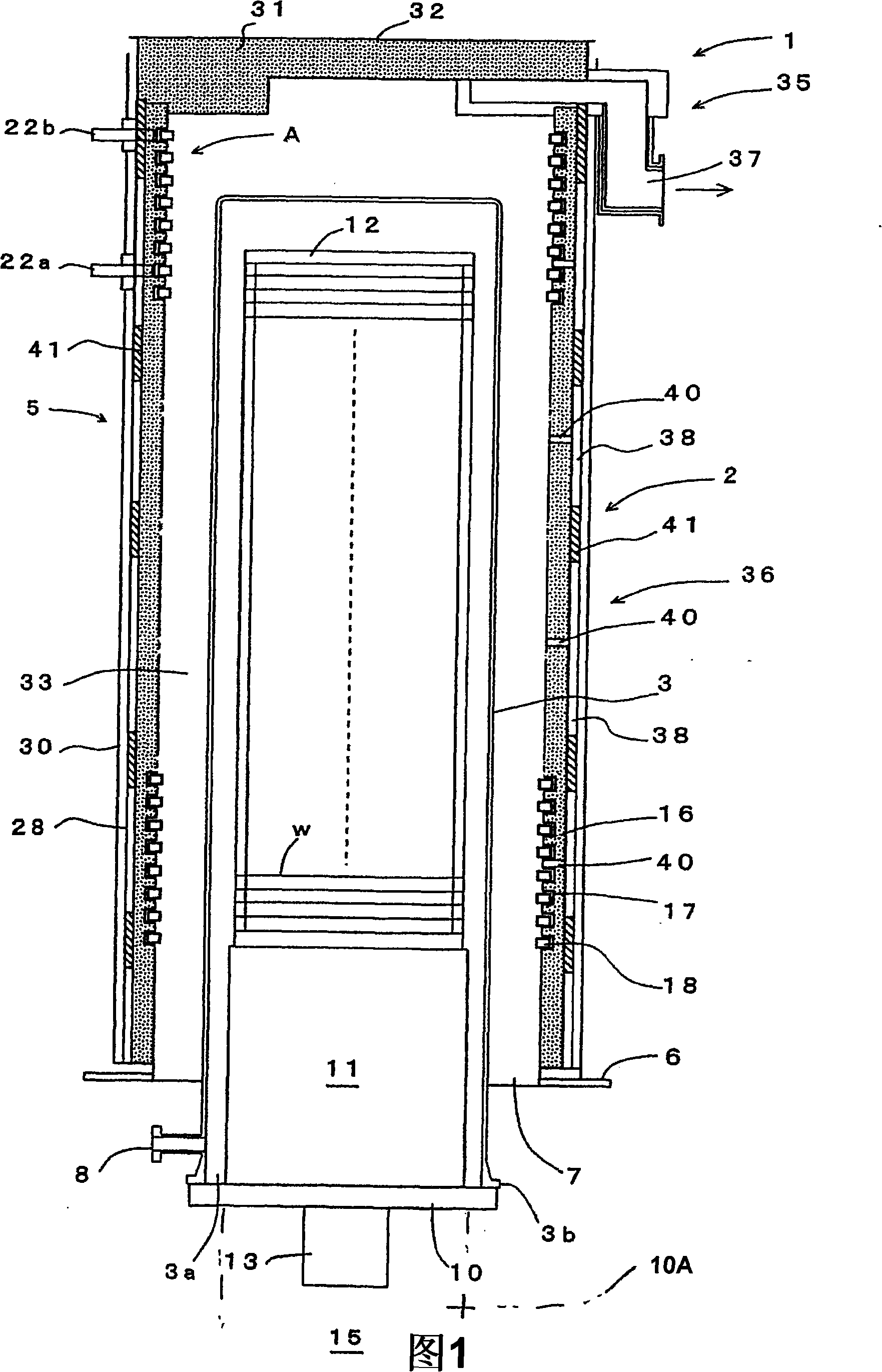
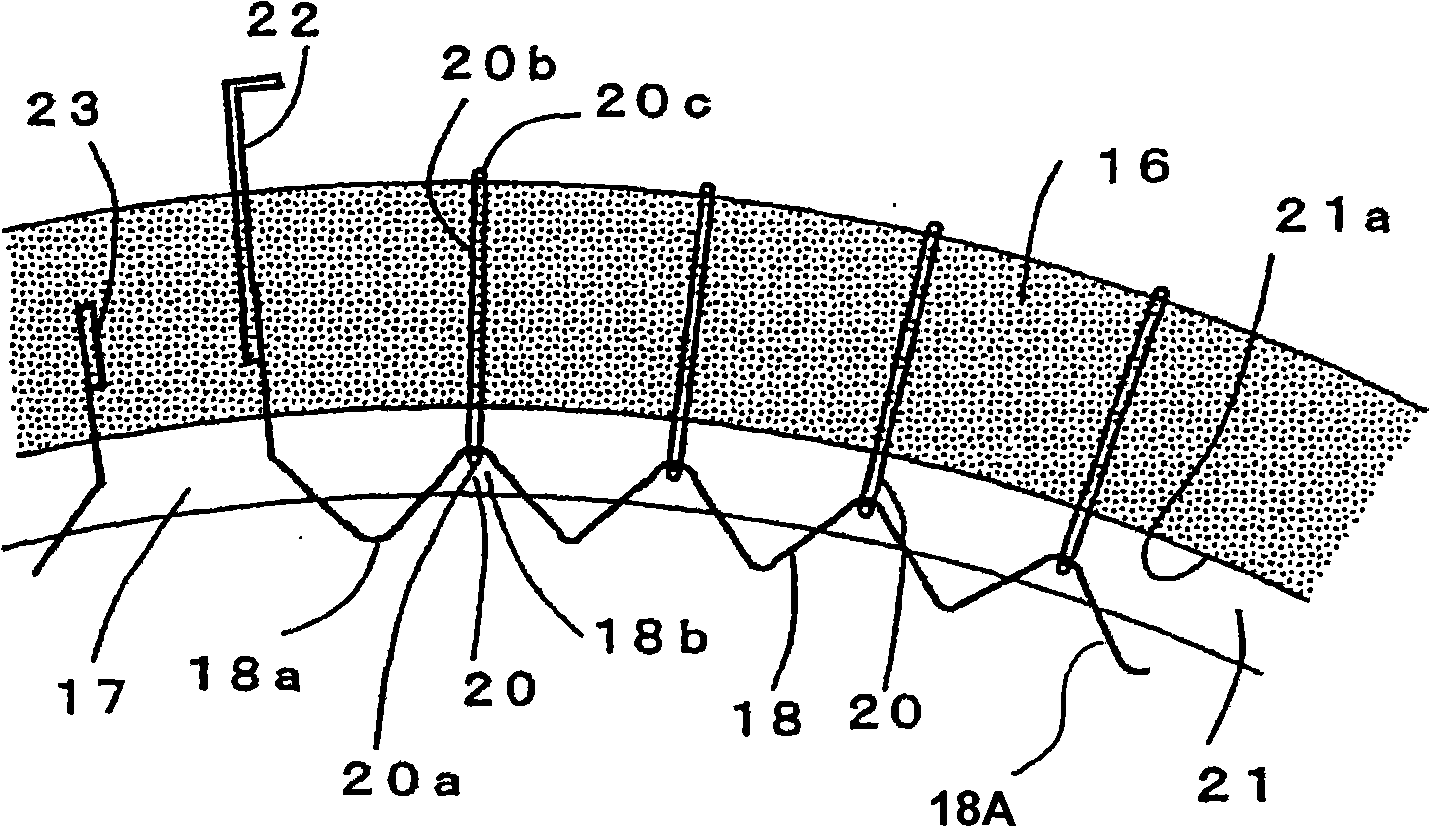
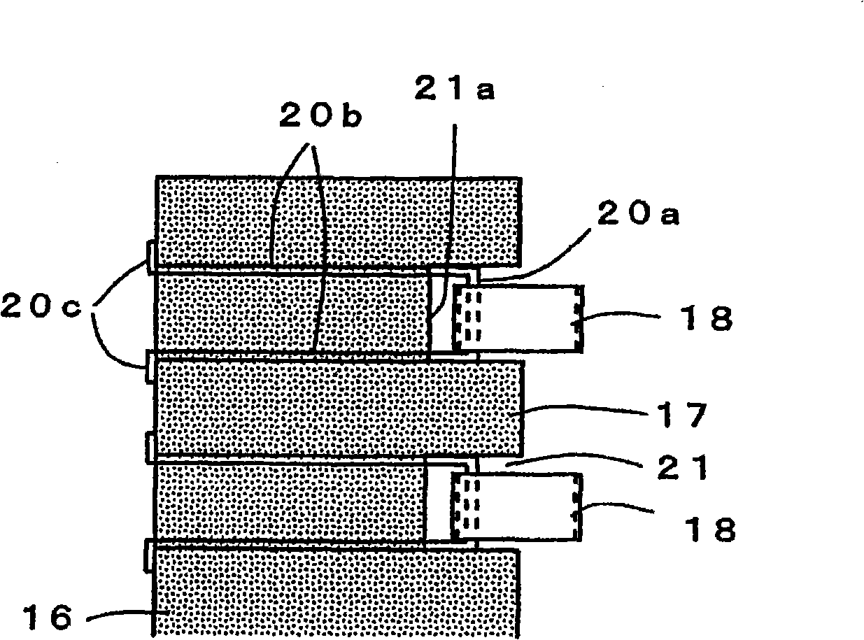
[0049] Hereinafter, the best mode for carrying out the present invention will be described in detail based on the drawings. Fig. 1 is a longitudinal sectional view schematically showing a vertical heat treatment apparatus as an embodiment of the present invention, figure 2 is an enlarged cross-sectional view showing part A of FIG. 1 , image 3 is an enlarged longitudinal sectional view showing part A, Figure 4 is a plan view showing the heating element, Figure 5 It is a side view showing a heating member.

[0050] In FIG. 1 , reference numeral 1 represents a vertical heat treatment apparatus as one of semiconductor manufacturing apparatuses, and this heat treatment apparatus 1 has a structure capable of accommodating a plurality of objects to be processed (such as semiconductor wafers w) at a time, and performing oxidation, diffusion, and reduction thereof. Vertical heat treatment furnace 2 for heat treatment such as pressure CVD. This heat treatment furnace 2 includes:...


PUM


Abstract

The invention provides a heat processing furnace and a vertical heat processing device capable of quickly increasing and decreasing a temperature, while achieving improvement in durability. A heat processing furnace (2) comprises: a processing vessel (3) for accommodating an object to be processed (w) and performing thereto a heat process; and a cylindrical heater (5) disposed to surround an outer circumference of the processing vessel (3), for heating the object to be processed (w). The heater (5) includes a cylindrical heat insulating member (16), and heating resistors (18) arranged along an inner circumferential surface of the heat insulating member (16). Each of the heating resistors (18) is formed of a strip-shaped member that is bent into a waveform having peak portions and trough portions. Pin members (20) are arranged in the heat insulating member (16) at suitable intervals therebetween, the pin members (20) holding the heating resistor (18) such that the heating resistor (18) is movable in a radial direction of the heater.

Description

technical field [0001] The present invention relates to a heat treatment furnace and a vertical heat treatment device with the heat treatment furnace. Background technique [0002] In the manufacture of semiconductor devices, various heat treatment apparatuses are used to perform oxidation, diffusion, CVD (Chemical Vapor Deposition) and other treatments on a semiconductor wafer as an object to be processed. This general heat treatment apparatus has a heat treatment furnace including: a processing vessel (reaction tube) for accommodating and heat-treating a semiconductor wafer; A heater (heating device) for heating the wafer. The heater includes: a cylindrical heat insulator; and a heating resistor provided on the inner peripheral surface of the heat insulator via a support. [0003] As the heating resistor, for example, in the case of a heat treatment apparatus capable of batch processing, a spiral heating member (also referred to as a heating wire or a heating resistor) a...

Claims


Application Information

Patent Timeline
IPC IPC(8): H01L21/00H05B3/64H05B3/66
CPCF26B23/06F27B17/0025H01L21/67098
Inventor 市川贵小林诚山贺健一
Owner TOKYO ELECTRON LTD
Learn More