
Stiffness-variable surgical manipulator, surgical instrument and operation method of surgical instrument

A surgical device and variable stiffness technology, applied in the field of medical devices, can solve the problems of inability to use in a narrow space, large noise and structural size, and large overall structure, and achieve the effects of simple structure, high degree of automation, and small size

Active Publication Date: 2019-08-16
SHANDONG UNIV
View PDF5 Cites 8 Cited by
  • Summary
  • Abstract
  • Description
  • Claims
  • Application Information

AI Technical Summary

Problems solved by technology

Such as using a locking mechanism based on sliders and stoppers to switch the state of the cannula system (compliance or rigidity), but the inventors found that the structural design of this method is quite complicated, and the overall structure is bulky, which cannot be narrowed during the operation. Use of space; apply the reversible interference of granular media (sand or coffee powder) and vacuum pressure to adjust the stiffness of the system, the inventors found that high stiffness requires a large number of particles, which will lead to a structure that is too bulky; by increasing the tension of the cables to To improve the rigidity of the surgical manipulator, the inventor found that this method requires high-strength and wear-resistant cable materials and the wiring arrangement is relatively complicated; a cylindrical silicone catheter is used and a mesh-shaped plastic tube is embedded inside to form a variable rigidity The inventors found that this method needs to use air pressure to control the stiffness, and the noise and structural size are relatively large, so it is not suitable for application in surgery. Therefore, there is no stiffness adjustment of multi-section continuum surgical robots that can meet clinical applications. technology

Method used


Image

  • Stiffness-variable surgical manipulator, surgical instrument and operation method of surgical instrument
  • Stiffness-variable surgical manipulator, surgical instrument and operation method of surgical instrument
  • Stiffness-variable surgical manipulator, surgical instrument and operation method of surgical instrument

Examples


Embodiment 2

[0043] This embodiment discloses a surgical device, which includes a base plate, a mechanical arm support is provided on one side of the base plate, and the mechanical arm support is fixedly connected to one end of the variable stiffness surgical mechanical arm described in Embodiment 1 through bolts. Specifically, the joint of the surgical manipulator with variable stiffness used to connect with the support of the manipulator is connected with a flange connection plate 7, and the flange connection plate is fixedly connected with the support of the manipulator through bolts.

[0044] Two first driving mechanisms are arranged on the bottom plate, the first driving mechanism adopts a steering gear, the steering gear is fixed on the support plate, the support plate and the bottom plate are fixedly connected by bolts, and the output shaft of the steering gear is connected to the turntable , the two ropes in one group of the variable stiffness surgical manipulator pass through the s...

Embodiment 3

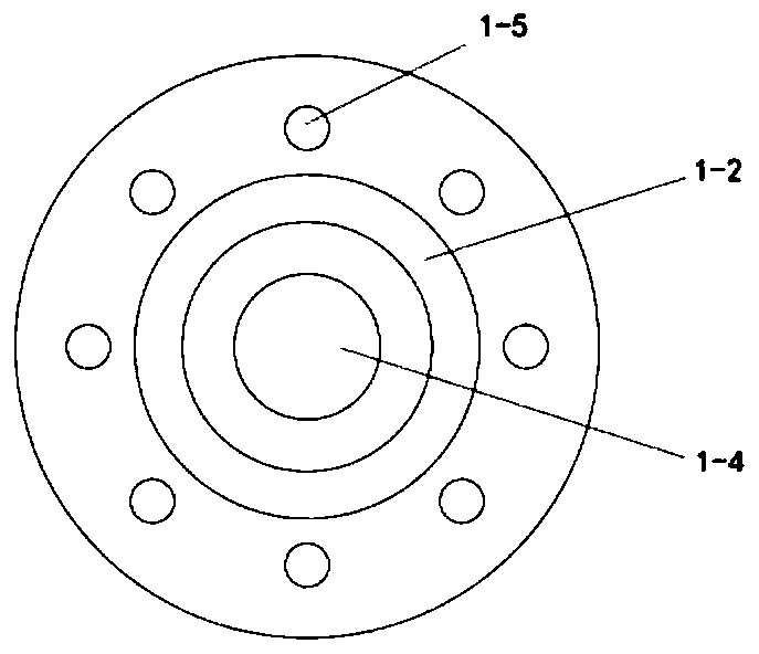
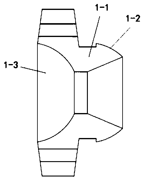
[0050] This embodiment discloses a surgical device, such as Figure 5-6 As shown, in this embodiment, the variable stiffness surgical manipulator includes a first manipulator part and a second manipulator part, and the number of its ropes is eight, a total of four groups of ropes, wherein two groups of ropes (four ropes) Pass through all the joints of the first mechanical arm and the second mechanical arm, and be fixedly connected with the joints at the end of the second mechanical arm. The other two sets of ropes (the other four ropes) only pass through the first mechanical arm and are connected with Joint fixed connection of the end of the first mechanical arm part (for connecting the end of the second mechanical arm part), wherein the first mechanical arm part is used to connect with the mechanical arm support 6, and the end of the second mechanical arm part is used for To connect the surgical instruments, the strings passing only through the first mechanical arm and the st...

Embodiment 4

[0059] This embodiment discloses a working method of a surgical device: input the motion path of the end of the mechanical arm to the controller in advance according to the surgical target position, connect the required surgical instruments to the end of the surgical mechanical arm with variable stiffness, and connect the flexible temperature control tube The positive and negative poles of the power supply are respectively connected to the water inlet and the water outlet. The flexible metal tube generates heat after being energized, and heats the variable stiffness tube made of PET plastic material. After heating to a certain temperature, the variable stiffness tube produces a phase change. , changing from rigidity to flexibility. At this time, the second motor works to drive the variable-stiffness surgical manipulator to move forward as a whole. While moving forward, the steering gear works together to work according to the movement path set by the controller to retract or rel...


PUM


Abstract

The invention relates to a stiffness-variable surgical manipulator, a surgical instrument and an operation method of the surgical instrument. The stiffness-variable surgical manipulator comprises multiple joints, the adjacent joints are in spherical contact, all the joints pass through a flexible pipe arranged concentrically with the joints, a flexible temperature control pipe wrapped outside theflexible pipe, a stiffness-variable pipe wrapped outside the flexible temperature control pipe, and at least one set of rope lines, the number of each set of rope lines is two, the rope lines are evenly distributed around the circle set concentrically with the joints, the diameter of the circumference is larger than the outer diameter of the stiffness-variable pipe, the two rope lines in the sameset are located at both ends of the circumferential diameter, and the flexible temperature control pipe can heat or cool the stiffness-variable pipe to change the stiffness state of the stiffness-variable pipe.

Description

technical field [0001] The invention relates to the technical field of medical instruments, in particular to a surgical robot arm with variable stiffness, a surgical device and a method. Background technique [0002] In endoscopic interventional surgery, the flexible surgical manipulator can flexibly adapt to the tortuous path of the human body in a narrow space without harming human tissue; however, when the end surgical instrument is working, the surgical manipulator needs to have sufficient rigidity to resist external loads. The stiffness in these two cases is quite different, and the inventors have found that existing surgical robots fail to fully meet these two conflicting requirements, which limits the performance and use of surgical robots. [0003] Current surgical manipulators adjust stiffness by reassembling or reconnecting components using attachable and detachable links within the structure. Consistency is obtained when parts are disassembled and high stiffness...

Claims


Application Information

Patent Timeline
Patent Type & Authority Applications(China)
IPC IPC(8): A61B34/30A61B17/00
CPCA61B17/00234A61B34/30A61B34/71A61B2034/301A61B2034/306
Inventor 杜付鑫卢佳佳张涛张钢孙海林王子豪杨浩锦
Owner SHANDONG UNIV
Learn More