Eureka AIR delivers breakthrough ideas for toughest innovation challenges, trusted by R&D personnel around the world.

Luminous diode base structure possessing horizontal heat diffusion member

A light-emitting diode and thermal diffusion technology, which is applied in the direction of electrical components, electric solid-state devices, semiconductor devices, etc., can solve the problems affecting the heat conduction and heat dissipation speed of the light-emitting diode base structure 10, the inability to carry the light-emitting diode 14, and general products without suitable structures and other issues to achieve the effect of increasing horizontal conduction capacity, improving product structure, and improving heat conduction

Inactive Publication Date: 2008-11-26
钜亨电子材料元件有限公司
View PDF1 Cites 3 Cited by
  • Summary
  • Abstract
  • Description
  • Claims
  • Application Information

AI Technical Summary

Problems solved by technology

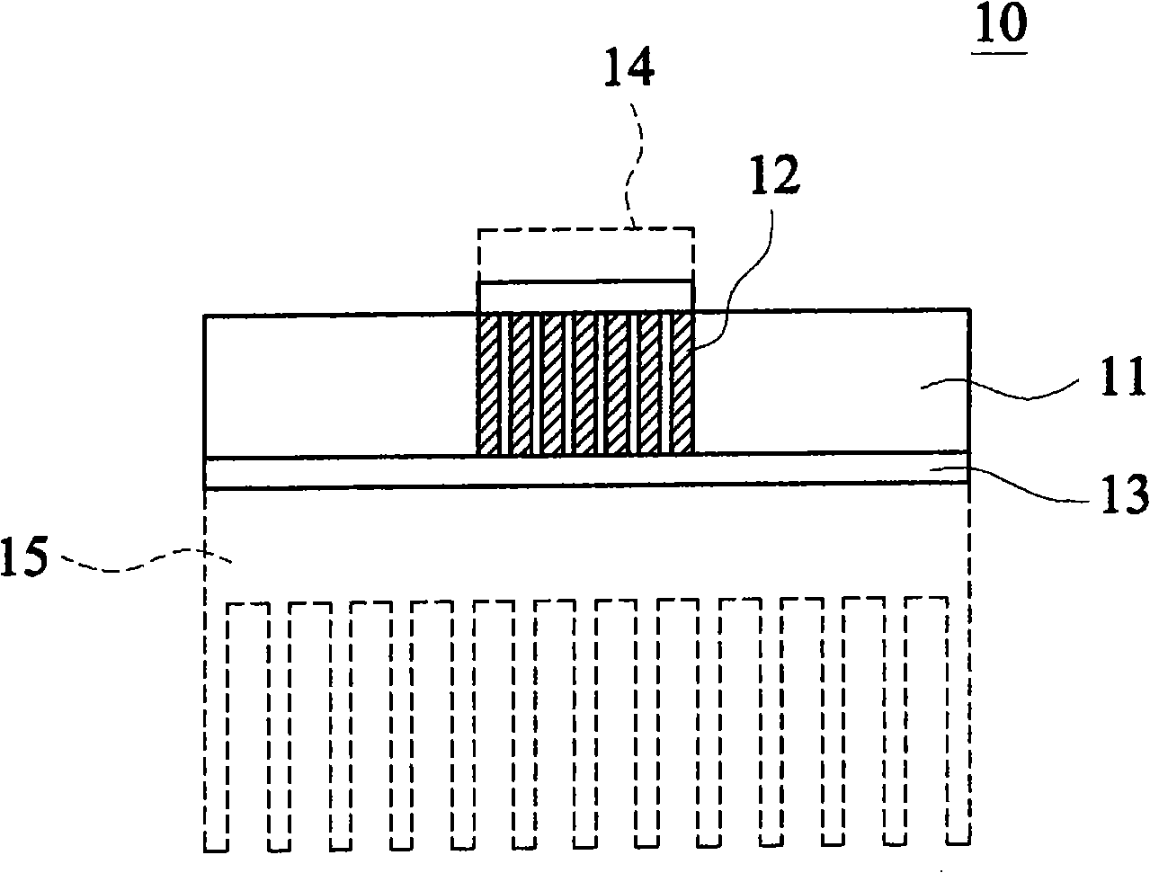
[0004] in such as figure 1 In the shown structure, a plurality of vertical heat conductors 12 are arranged in the low-temperature co-fired multilayer ceramic substrate 11 to provide a vertical heat conduction path, but because the vertical heat conductors 12 conduct heat to the metal substrate 13, it will cause heat dissipation. It is easy to concentrate on a single point of the metal substrate 13, so that the heat is unevenly distributed on the metal substrate 13, because the heat source is excessively concentrated, which seriously affects the heat conduction and heat dissipation speed of the LED base structure 10
[0005] In the above-mentioned prior art, because only the longitudinal heat conductor 12 is provided in the base of the LED base structure 10, the conduction of the heat source in the horizontal direction is not good, so the speed of heat dissipation cannot be improved.
As the wattage of the LED 14 continues to increase, so that the heat energy generated by the LED 14 continues to increase, the LED base structure 10 must be capable of carrying a higher wattage LED 14, so if the existing conventional The light emitting diode base structure 10 is bound to be unable to carry higher wattage light emitting diodes 14
[0006] It can be seen that the above-mentioned existing light-emitting diode base structure obviously still has inconvenience and defects in structure and use, and needs to be further improved urgently.
In order to solve the above-mentioned problems, the relevant manufacturers have tried their best to find a solution, but for a long time no suitable design has been developed, and the general product has no suitable structure to solve the above-mentioned problems. This is obviously the relevant industry. Urgent problem

Method used


Image

  • Luminous diode base structure possessing horizontal heat diffusion member
  • Luminous diode base structure possessing horizontal heat diffusion member
  • Luminous diode base structure possessing horizontal heat diffusion member

Examples


Embodiment Construction

[0048] In order to further explain the technical means and effects of the present invention to achieve the intended purpose of the invention, the specific implementation of the light-emitting diode base structure with horizontal thermal diffusion parts proposed according to the present invention will be described below in conjunction with the accompanying drawings and preferred embodiments. , structure, feature and effect thereof, detailed description is as follows.

[0049] The aforementioned and other technical contents, features and effects of the present invention will be clearly presented in the following detailed description of preferred embodiments with reference to the drawings.

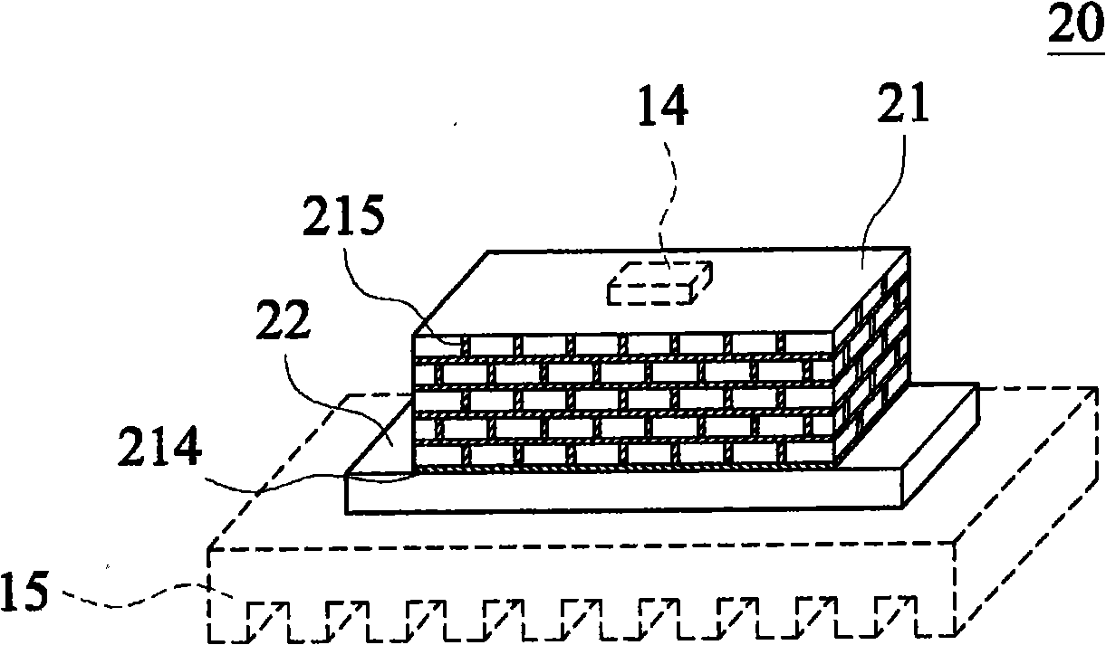
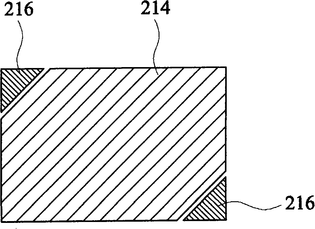
[0050] see Figure 2 to Figure 5C as shown, figure 2 It is a three-dimensional schematic view of an embodiment of an LED base structure 20 with a horizontal heat spreading member in the present invention. Figure 3A It is a bottom view of a base embodiment of a LED base structure 20 of the...


PUM


Abstract

The invention relates to a light emitting diode seat structure with a horizontal thermal diffusion member, comprising a seat body and a horizontal thermal diffusion member. The seat body is a co-fired multilayer ceramic base material with a first surface and a second surface, and the first surface and the second surface are respectively provided with a first heat conducting layer and a second heat conducting layer. Heat conducting bodies which are longitudinally and transversely mutually interlaced and connected are arranged in the seat body, and the heat conducting bodies are respectively in heat-conducting combination with the first heat conducting layer and the second heat conducting layer. The horizontal thermal diffusion member is provided with a first contact surface and a second contact surface, wherein the first contact surface and the second contact surface are in heat-conducting combination. By the longitudinal and transverse arrangement of the heat conducting bodies inside the seat body, heat energy generated by the light emitting diode can be acceleratively conducted to the horizontal thermal diffusion member, and then the heat energy is conducted out of the light emitting diode seat body via the horizontal thermal diffusion member. The light emitting diode seat structure combining the seat body and the horizontal thermal diffusion member can enable the seat structure to have better heat conducting efficiency.

Description

technical field [0001] The present invention relates to a light-emitting diode base structure, in particular to a light-emitting diode base structure with a horizontal thermal diffusion part for carrying a light-emitting diode, which can improve the heat conduction efficiency of the light-emitting diode. Background technique [0002] see figure 1 As shown, it is a cross-sectional view of the LED base structure 10 in the prior art. In order to make the application level of the light emitting diode 14 more extensive, and then be applicable in daily life, improving the luminous efficiency of the light emitting diode 14 is the main goal of the current industry efforts. Because most of the input power of the light emitting diode 14 is converted into heat energy at present, but cannot be effectively converted into light energy, if the heat conduction and heat dissipation speed of the light emitting diode base structure 10 can be improved, the input power of the light emitting dio...

Claims


Application Information

Patent Timeline
Patent Type & Authority Applications(China)
IPC IPC(8): H01L33/00H01L23/367H01L33/64
Inventor 杨富宝陈明鸿
Owner 钜亨电子材料元件有限公司
Why Eureka
Eureka Blog
Learn More