
Antenna arrays with dual circular polarization

An antenna array and component technology, applied in antenna arrays, antenna unit combinations with different polarization directions, antennas, etc.

Inactive Publication Date: 2008-11-26
THOMSON LICENSING SA
View PDF3 Cites 13 Cited by
  • Summary
  • Abstract
  • Description
  • Claims
  • Application Information

AI Technical Summary

Problems solved by technology

[0003] A major issue for the economic viability of the system is to manufacture low-cost user terminals such that it is possible to comply with all specifications

Method used


Image

  • Antenna arrays with dual circular polarization
  • Antenna arrays with dual circular polarization
  • Antenna arrays with dual circular polarization

Examples


Embodiment Construction

[0035] Circuits according to the prior art have been briefly described above and will not be described again hereafter.

[0036] For example, circular polarization is obtained by methods known to those skilled in the art, which include employing radiating elements with mutually orthogonal linear polarizations and exciting them in orthogonal phases.

[0037] Therefore, on a single radiating element of the patch type, it is sufficient to excite two orthogonal sides through two ports and impose a 90° phase difference between them to produce circular polarization. Cross polarization will be obtained by inversion of the phase difference between the ports.

[0038] With two patches, it is sufficient to excite each patch such that its excitation is in quadrature and the phase shift between ports is 90°.

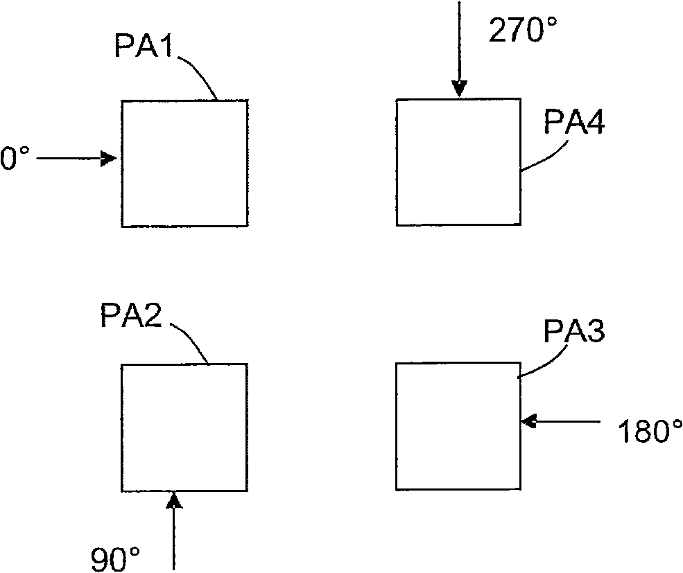
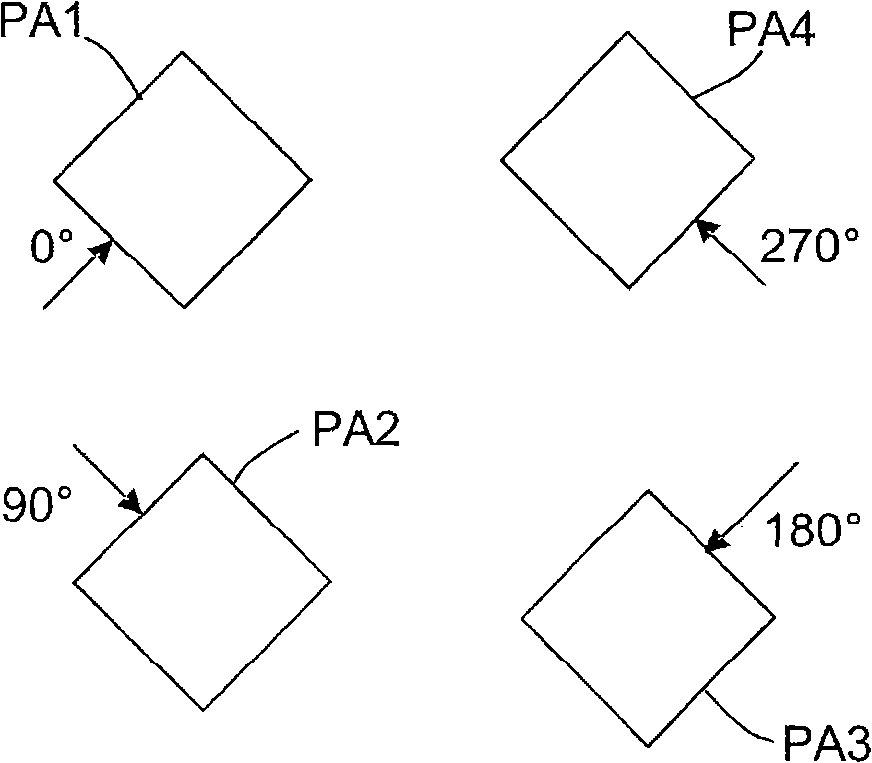
[0039] Furthermore, in order to increase the bandwidth of the network, sequential rotation techniques are used. Figure 2a A basic diagram showing the technique. Each of the four...


PUM


Abstract

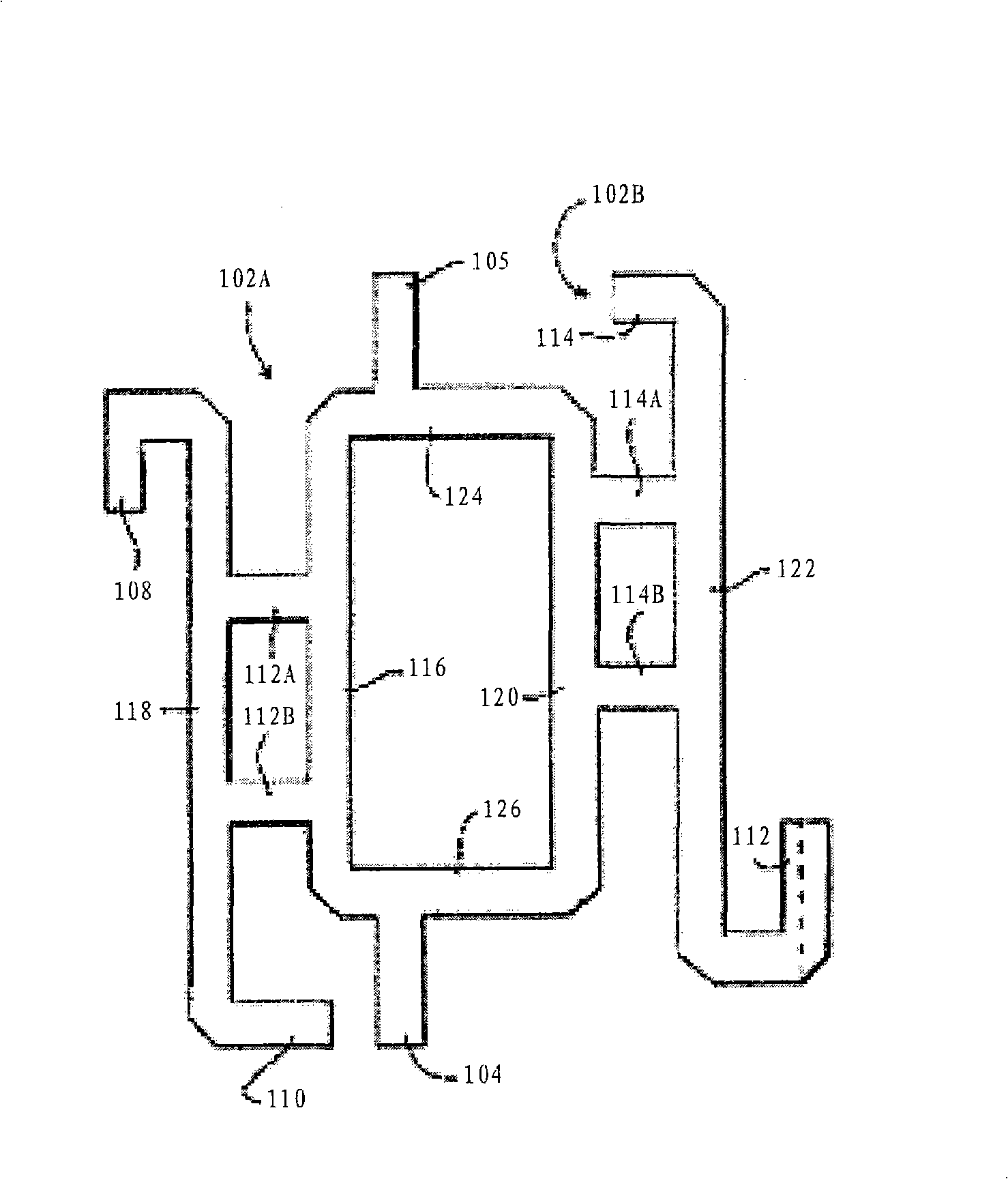
The invention consists of an antenna array, for the reception of two frequency bands, comprising two pairs of radiating elements and an network for excitation of these elements for the reception of one of the bands. The radiating elements are positioned so as to free the center of the array to allow colocalized reception of the other band. The excitation network comprises hybrid elements so as to introduce a certain phase shift between the radiating elements allowing a dual circular polarization . This network must comply with two constraints:The phase shift introduced between the hybrids must be equal to the phase shift of the hybrid modulo 2ktt, .k integer, and the length of the line L1 placed between the first hybrid H1 and the first patch PA1 is such that it introduces a phase shift equal to p modulo 2ktt, .k integer.

Description

technical field [0001] The present invention pertains to dual circularly polarized antenna arrays, and more particularly to antennas capable of transmitting and receiving in different frequency bands such as in particular in the K / Ka band (for Internet services, 20 / 30 GHz) and the Ku band (for TV reception, 10 / 30 GHz). 15GHz) signal antenna array. Background technique [0002] Satellite links make it possible to cover huge geographic spans without requiring a prohibitively high investment for operators or users. [0003] A major issue for the economic viability of the system is to manufacture low-cost user terminals such that it is possible to comply with all specifications. [0004] In order to increase the amount of functionality and consequently make the product more attractive, user terminals must allow access to high-speed Internet as well as traditional TV reception services. [0005] The user terminals consist of an indoor unit or IDU, which is a monitoring unit and...

Claims


Application Information

Patent Timeline
IPC IPC(8): H01Q21/00H01Q9/04H01Q21/28H01Q21/24
CPCH01Q9/0407H01Q21/28H01Q21/0006H01Q21/24H01Q3/36H01Q5/10
Inventor 让-弗朗索瓦·平托斯菲利普·米纳德菲利普·钱贝林
Owner THOMSON LICENSING SA
Learn More