High-efficiency drying apparatus for regenerating exhaust heat of pressure gas

A technology of compressed gas and drying equipment, which is applied in the direction of gas treatment, dispersed particle separation, membrane technology, etc. It can solve the problems of increasing the dew point temperature of the product gas, reducing the adsorption capacity of the adsorbent, and incomplete regeneration, so as to solve the problem of incomplete regeneration , reduce blowing cooling time, improve the effect of utilization

Inactive Publication Date: 2008-12-03
周才宝
View PDF1 Cites 9 Cited by
  • Summary
  • Abstract
  • Description
  • Claims
  • Application Information

AI Technical Summary

Problems solved by technology

[0002] The conventional waste heat (i.e. compression heat) regenerative drying device needs to use part of the product gas as the regeneration gas when regenerating the adsorbent to purge, cool the adsorbent and then vent it, thus consuming a certain amount of product gas; Chinese patent application documents (Application No. : 200610032638.9) Although the disclosed method does not consume regeneration gas, it uses saturated gas at normal temperature as the regeneration gas source; due to the high temperature and high water content of the regeneration gas, the adsorbent absorbs moisture prematurely, and the regeneration is not complete, which improves the dew point of the finished gas temperature, which reduces the adsorption capacity of the adsorbent

Method used


Image

  • High-efficiency drying apparatus for regenerating exhaust heat of pressure gas
  • High-efficiency drying apparatus for regenerating exhaust heat of pressure gas
  • High-efficiency drying apparatus for regenerating exhaust heat of pressure gas

Examples


Embodiment Construction

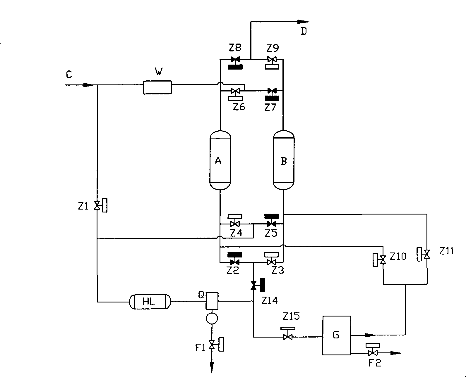
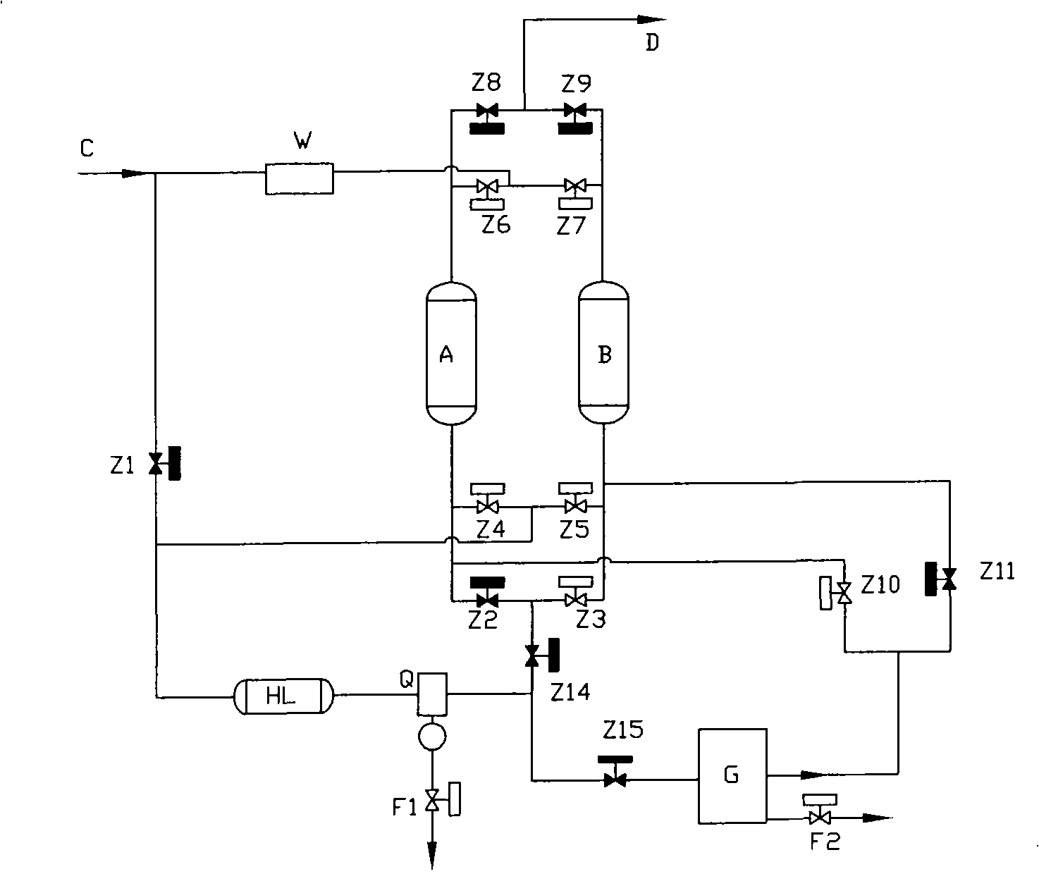
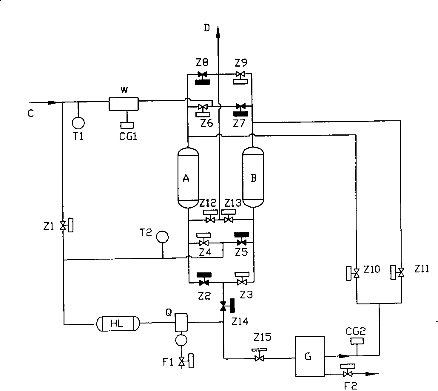
[0028] figure 1 , figure 2 In the shown embodiment, the high-efficiency drying device for regeneration of compressed gas waste heat includes two drying towers; the gas flow enters from the input port C and is divided into two pipelines; the first pipeline is connected in parallel to two drying pipelines, and then connected in series After connecting two regulating valves Z14 and Z15, it is connected to the inlet of the freeze dryer G (the freeze dryer G is also connected to the drain valve F2); the first drying pipeline is connected in series with the valve Z7, the forward inlet of the drying tower B and the valve Z3, the second drying pipeline is connected in series with valve Z6, the forward inlet of drying tower A and valve Z2; Connect the valve Z10 with the pipeline, connect the reverse inlet of the drying tower B with the valve Z11) through the pipeline and connect it in parallel, and then connect the G outlet of the freeze dryer. The second pipeline (with valve Z1) is...


PUM


Abstract

The invention relates to a compressed gas drying device. The invention aims to provide the device with characteristics of complete regeneration of an adsorbent and lower outlet air pressure dew point. The invention adopts the technical proposal that: in a compressed gas waste heat regeneration high-efficiency drying device, a first path of pipeline is connected with at least two drying pipelines in parallel, and then is connected with an inlet of a freeze drier after the first path of pipelines is orderly connected with two adjusting valves in series; each drying pipeline is orderly connected with a valve and a forward inlet of a drying tower in series; a pipeline on an outlet of the freeze drier is divided into at least two branch paths, wherein, each branch path is connected with a valve, and then is connected to a reverse inlet of the drying tower; a second path of pipeline is divided into two branch paths; the first branch path is divided into at least two shunts; each shunt is connected with a valve, and then is connected with a reverse inlet of the drying tower; the second shunt is connected between the two adjusting valves through a water cooler and a gas-liquid separator in sequence; and the forward inlets of the drying towers are connected with a valve respectively, and then are connected with an air outlet in parallel.

Description

technical field [0001] The invention relates to a high-efficiency drying device for regeneration of compressed gas waste heat. Background technique [0002] The conventional waste heat (i.e. compression heat) regenerative drying device needs to use part of the product gas as the regeneration gas when regenerating the adsorbent to purge, cool the adsorbent and then vent it, thus consuming a certain amount of product gas; Chinese patent application documents (Application No. : 200610032638.9) Although the disclosed method does not consume regeneration gas, it uses saturated gas at normal temperature as the regeneration gas source; due to the high temperature and high water content of the regeneration gas, the adsorbent absorbs moisture prematurely, and the regeneration is not complete, which improves the dew point of the finished gas temperature, which reduces the adsorption capacity of the adsorbent. Contents of the invention [0003] The technical problem to be solved by ...

Claims


Application Information

Patent Timeline
Patent Type & Authority Applications(China)
IPC IPC(8): B01D53/26
CPCB01D53/261B01D2259/402
Inventor 周才宝
Owner 周才宝
Why Eureka
Try Eureka