Multifunctional earthquake emergency system
An emergency system, multi-functional technology, applied in the field of electronics and information, can solve the problems of death of buried and injured people, lack of equipment, great impact on rescue work, etc.
- Summary
- Abstract
- Description
- Claims
- Application Information
AI Technical Summary
Problems solved by technology
Method used
Image

Examples
Embodiment Construction
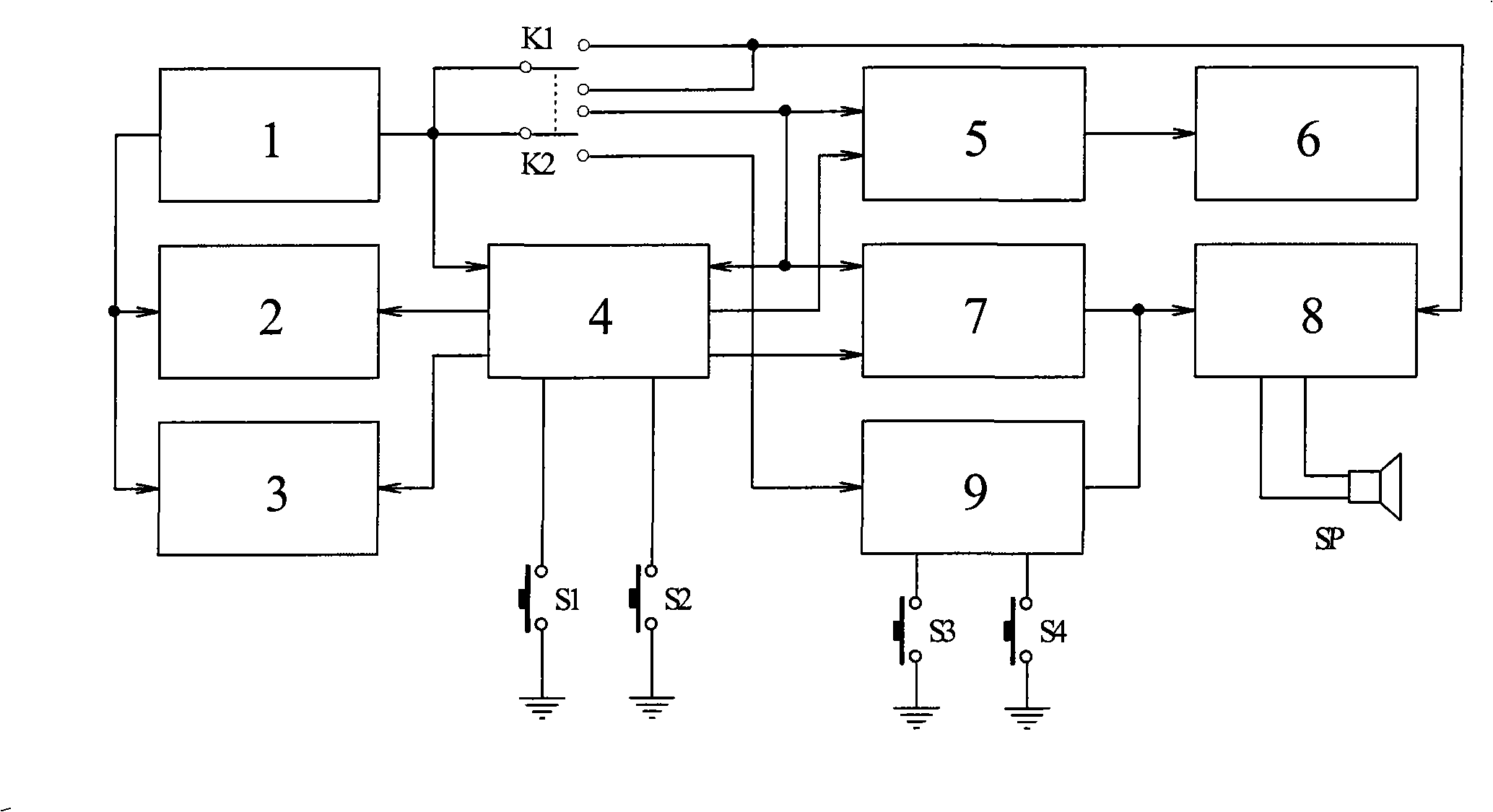
[0009] The principle block diagram of the multifunctional earthquake emergency system is shown in the attached figure: 1 is the power supply, 2 is the LCD electronic clock, 3 is the LED flashlight, 4 is the single-chip microcomputer, 5 is the radio frequency distress circuit, 6 is the transmitting antenna, 7 is the audio frequency distress circuit, 8 is the BTL power amplifier, 9 is FM radio, the whole system also includes double switch K1K2, button S1S2S3S4 and speaker SP.
[0010] The whole system takes the single-chip microcomputer 4 as the core, and controls the LCD electronic clock 2, the LED flashlight 3, the radio frequency distress call 5, and the audio frequency distress call 7, and only the radio 9 is independent of the single-chip microcomputer. The power supply 1 of the whole system is powered by two to three AA or AA alkaline dry batteries. After installing the batteries, the LCD electronic clock 2 starts to work. The electronic clock consumes very little power. It...
PUM
 Abstract
Description
Claims
Application Information
 - R&D
- Intellectual Property
- Life Sciences
- Materials
- Tech Scout
- Unparalleled Data Quality
- Higher Quality Content
- 60% Fewer Hallucinations
Browse by: Latest US Patents, China's latest patents, Technical Efficacy Thesaurus, Application Domain, Technology Topic, Popular Technical Reports.
© 2025 PatSnap. All rights reserved.Legal|Privacy policy|Modern Slavery Act Transparency Statement|Sitemap|About US| Contact US: help@patsnap.com