Glue spreading apparatus, using and maintaining method for the glue spreading apparatus

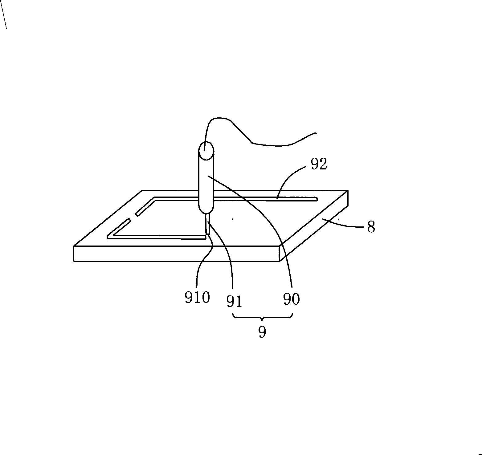
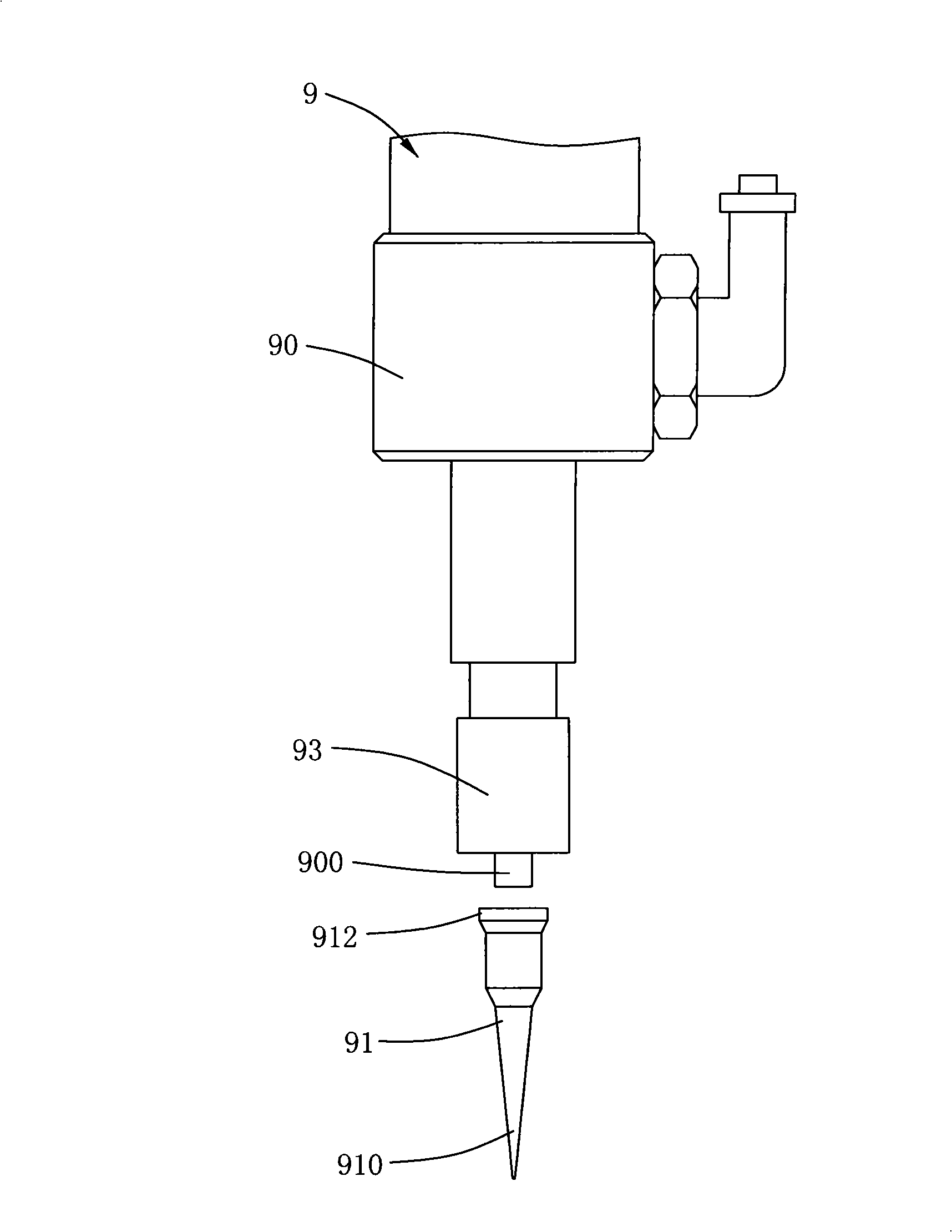
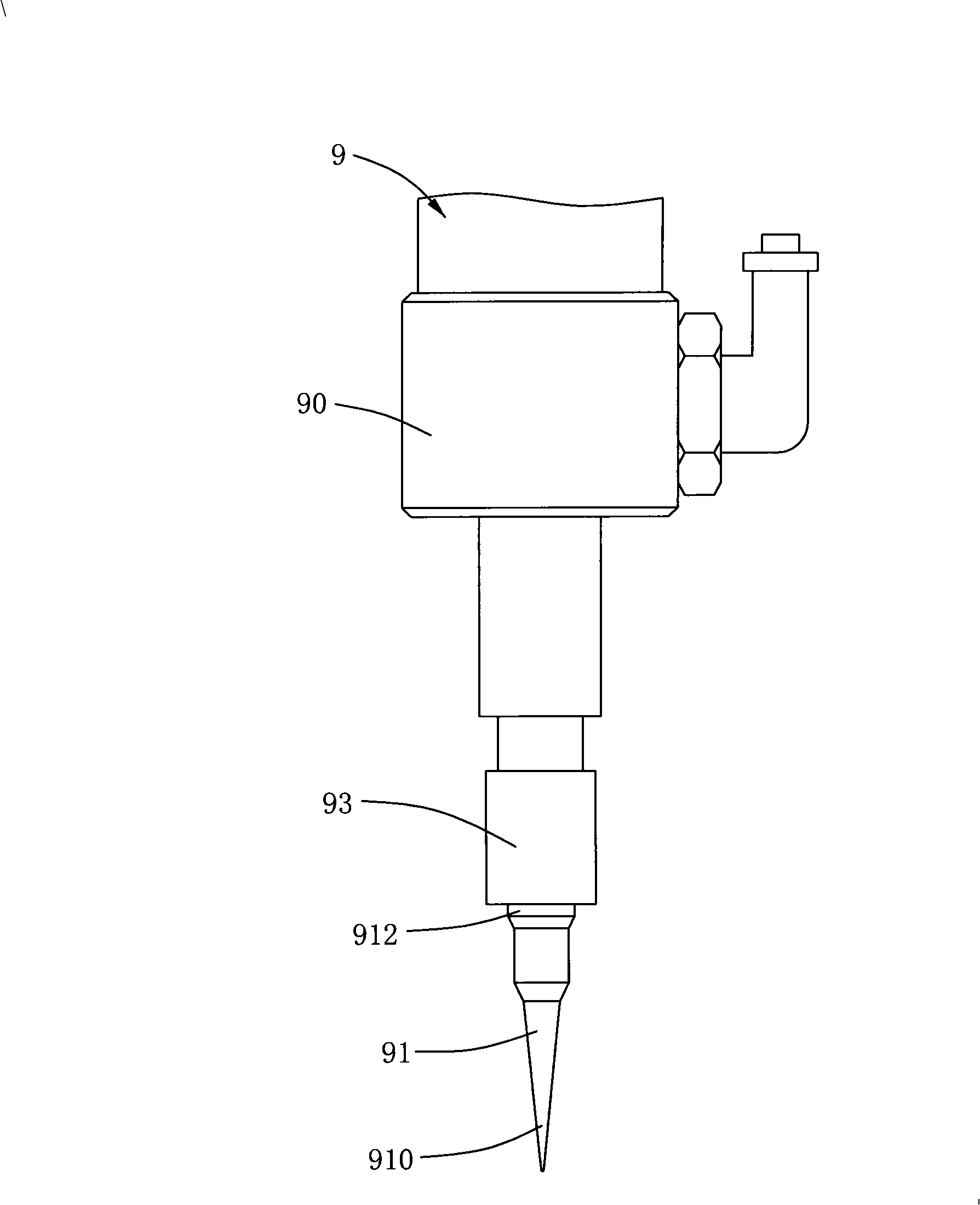
A gluing device and gluing technology, which are applied to the device, spray device, coating and other directions for applying liquid to the surface, can solve the problem that the gluing needle 91 is easy to bend, etc., and achieve the improvement of gluing quality and gluing. Efficiency, improving work efficiency, and correcting the effect of the assembly position

Inactive Publication Date: 2008-12-10
AU OPTRONICS (XIAMEN) CORP +1
View PDF6 Cites 13 Cited by
  • Summary
  • Abstract
  • Description
  • Claims
  • Application Information

AI Technical Summary

Problems solved by technology

In detail, the top end of the glue applicator 91 is placed on the glue outlet 900 of the glue valve 90, and then the top 912 of the glue applicator 91 is fixed on the glue valve 90 through the rotating fixing mechanism 93, but the glue The bottom end 910 of the needle 91 is not fixed, which cannot solve the problem that the gluing needle 91 is easy to bend

Method used


Image

  • Glue spreading apparatus, using and maintaining method for the glue spreading apparatus
  • Glue spreading apparatus, using and maintaining method for the glue spreading apparatus
  • Glue spreading apparatus, using and maintaining method for the glue spreading apparatus

Examples


Embodiment Construction

[0028] The following descriptions of the various embodiments refer to the accompanying drawings to illustrate specific embodiments in which the present invention can be practiced. The directional terms mentioned in the present invention, such as "up", "down", "front", "back", "left", "right", "top", "bottom", etc., are only for reference to the attached drawings. direction. Therefore, the directional terms used are used to illustrate and understand the present invention, but not to limit the present invention.

[0029] In the following embodiments, the same parts are denoted by the same symbols in different drawings.

[0030] Please refer to the gluing device 1 of a preferred embodiment of the present invention shown in the third A figure and the third B figure, the gluing device 1 includes: a machine base 10, a needle seat 20, a gluing needle 30, a fixing mechanism 40 and Needle protection mechanism 50 .

[0031] In this embodiment, the machine base 10 has the function of ...


PUM


Abstract

The invention discloses a rubberizing device, comprising a base, a pin base, a rubberizing pin on the pin base, a fixing mechanism and a pin protecting mechanism. In an embodiment of the invention, the fixing mechanism comprises a slide block and a clamp; wherein the slide block can be arranged on a guide rail of the base in a sliding way, and drives the pin base and the rubberizing pin to lift up and down to adjust the distance between the fixing mechanism and the pin protecting mechanism; the clamp is connected with the slide block to clamp the pin base. The pin protecting mechanism comprises a conical tube; the conical tube can be separately sheathed on the outside of the rubberizing pin. During the use and maintenance of the rubberizing device, when the distance between the fixing mechanism and the pin protecting mechanism is increased, the rubberizing pin can be moved out of the pin protecting mechanism thus realizing quick replacement and improving the operation efficiency.

Description

【Technical field】 [0001] The present invention relates to a gluing device and a method for using and maintaining the gluing device, in particular to a gluing device with a needle protection mechanism and a method for using and maintaining the gluing device. 【Background technique】 [0002] At present, glue applicators have been widely used in various electronic devices such as batteries, circuit boards, integrated circuits (IC) or liquid crystal displays (LCD) for sealing, dispensing or glue coating, etc., and glue applicators Quality has a great impact on the packaging quality of electronic devices, especially as packaging technology is improving day by day in the electronics manufacturing industry, the performance requirements for glue applicators have also become very high. [0003] Please refer to figure 1 The existing gluing machine 9 shown has a glue valve 90 and a gluing needle 91, wherein the gluing valve 90 is used to control the glue flow, and the gluing needle 91 ...

Claims


Application Information

Patent Timeline
Patent Type & Authority Applications(China)
IPC IPC(8): B05C5/02B05D7/24B05B15/00
Inventor 张毅
Owner AU OPTRONICS (XIAMEN) CORP
Why Eureka
Try Eureka