Apparatus and method for recovering carbon dioxide from flue gas using ammonia water

A carbon dioxide and flue gas technology, applied in chemical instruments and methods, separation methods, inorganic chemistry, etc., can solve problems such as temperature rise, deterioration effect, and temperature aggravated ammonia volatilization

Inactive Publication Date: 2008-12-10
POHANG IRON & STEEL CO LTD +1
View PDF1 Cites 20 Cited by
  • Summary
  • Abstract
  • Description
  • Claims
  • Application Information

AI Technical Summary

Problems solved by technology

Therefore, the case of using high-concentration ammonia water has disadvantages because a considerable amount of ammonia comes into contact with the gas in the upper part of the absorption tower before acting as an absorbent in the absorption tower, thereby volatilizing
[0012] In addition, as mentioned above, due to the absorption ...

Method used


Image

  • Apparatus and method for recovering carbon dioxide from flue gas using ammonia water
  • Apparatus and method for recovering carbon dioxide from flue gas using ammonia water
  • Apparatus and method for recovering carbon dioxide from flue gas using ammonia water

Examples


example 1

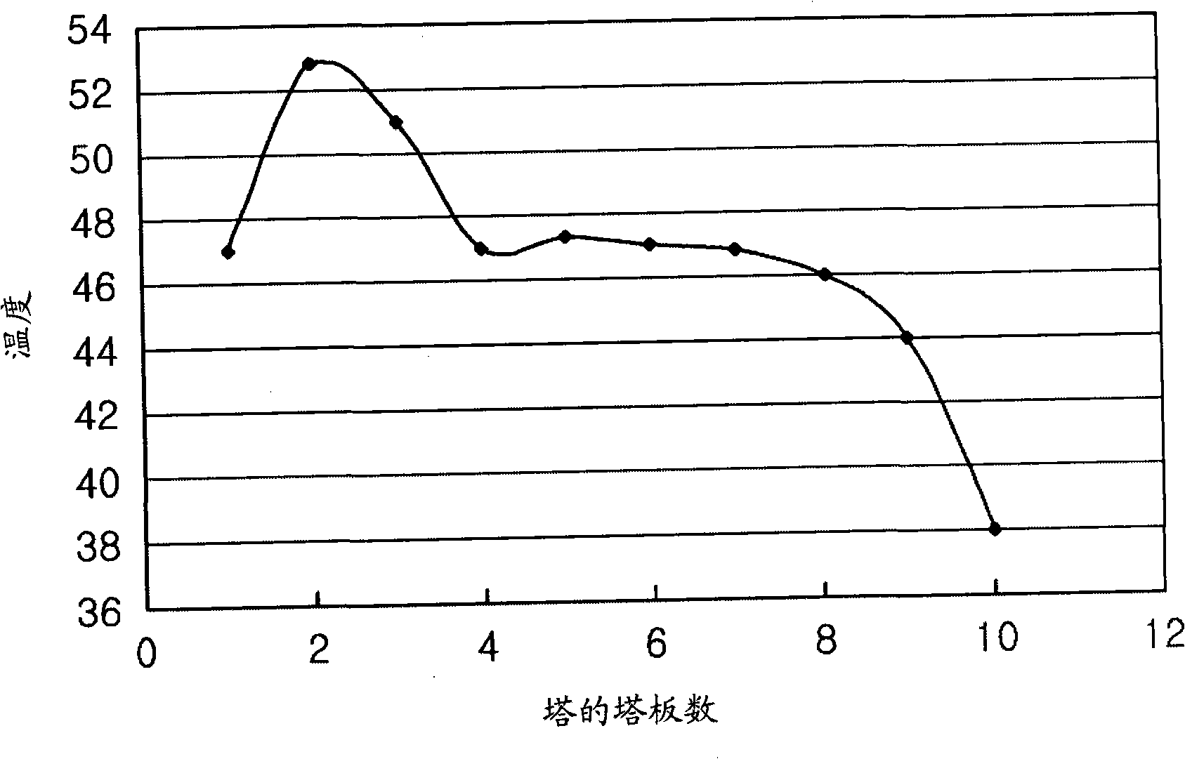
[0049] Adopt the absorption tower with the same structure and size as in the comparative example and the model gas with the same composition, reclaim the absorbent from the fourth column plate from the top of the absorption tower, cool the absorbent to 30 ° C, and then The absorbent is again supplied to the fourth tray from the top of the absorption column, wherein said fourth tray has the highest temperature. In this way, the amount of absorbent recovered is 1 / 6 of the amount initially supplied to the absorption tower.

[0050] As a result of Example 1, the temperature distribution inside the absorption tower is shown at Figure 4 middle. The carbon dioxide absorption efficiency was determined to be 88%.

example 2

[0052] Adopt the absorption tower with the same structure and size as in the comparative example and the model gas with the same composition, recover the absorbent from the fourth column plate from the top of the absorption tower, cool the absorbent to 20 ° C, and then The absorbent is again supplied to the fourth tray from the top of the absorption column, wherein said fourth tray has the highest temperature. In this way, the amount of absorbent recovered is 1 / 3 of the amount initially supplied to the absorption tower.

[0053] As a result of Example 2, the temperature distribution inside the absorption tower is shown at Figure 5 middle. The carbon dioxide absorption efficiency was determined to be 91%.

example 3

[0055] Adopt the absorption tower with the same structure and size in the comparative example and the model gas with the same composition, by reclaiming the absorbent from the fourth column tray from the top of the absorption tower, cooling the absorbent to 25°C, and then The absorbent is again supplied to the third tray from the top of the absorption column, wherein said fourth tray has the highest temperature. In this way, the amount of absorbent recovered is 1 / 3 of the amount initially supplied to the absorption tower.

[0056] As a result of Example 3, the temperature distribution inside the absorption tower is shown at Figure 6 middle. The carbon dioxide absorption efficiency was determined to be 91%.

[0057] It is clear from Examples 1 to 3 that part of the high-temperature absorbent is recovered and cooled by a recirculation cooler, and then supplied again to the absorption tower, thus significantly improving the CO2 absorption compared to the CO2 absorption efficie...


PUM

PropertyMeasurementUnit
Diameteraaaaaaaaaa
Heightaaaaaaaaaa

Abstract

An apparatus and method for absorbing and recovering carbon dioxide from flue gas using ammonia water as an absorbent, including an absorption column and a circulation cooler connected to the absorption column so that a high-temperature absorbent is recovered from the absorption column, cooled to a preset temperature, and then supplied again into the absorption column, in order to dissipate absorptive heat generated when carbon dioxide is absorbed from the flue gas.

Description

technical field [0001] The present invention relates to a kind of equipment and method for recovering carbon dioxide from flue gas by using ammonia water, more specifically, to such a kind of equipment and method for recovering carbon dioxide from flue gas by using ammonia water, that is, when using ammonia water to recover carbon dioxide from flue gas The absorption heat generated in the carbon dioxide process is effectively dissipated, and the formation of ammonium salts is minimized, thereby improving the recovery efficiency of carbon dioxide. Background technique [0002] Generally, methods for absorbing and recovering carbon dioxide from flue gas include adsorption, absorption, and membrane separation. [0003] Among these methods, the absorption method is a process of absorbing and recovering carbon dioxide from flue gas using an absorbent. As such, typical examples of absorbents are amine compounds. However, since amine compounds are expensive, the case of using ami...

Claims


Application Information

Patent Timeline
IPC IPC(8): C01B31/20B01D53/62C01B32/50
CPCY02C20/40Y02P20/151B01D53/14
Inventor 姜淇俊李英凤金光贤金济荣
Owner POHANG IRON & STEEL CO LTD
Why Eureka
Try Eureka