Electirc sliding contact and method for processing the same

A sliding contact and sliding surface technology, applied in the field of electrical contacts, can solve the problem of not being able to know the relationship of the sliding contacts, and achieve the effects of good electrical compatibility, improved rectification, and increased parallel impedance.

Inactive Publication Date: 2008-12-10
GERHARD PRAZISIONSPRESSTECHN
View PDF7 Cites 19 Cited by
  • Summary
  • Abstract
  • Description
  • Claims
  • Application Information

AI Technical Summary

Problems solved by technology

The relationship to sliding contacts is not known in this document

Method used


Image

  • Electirc sliding contact and method for processing the same
  • Electirc sliding contact and method for processing the same
  • Electirc sliding contact and method for processing the same

Examples


Embodiment Construction

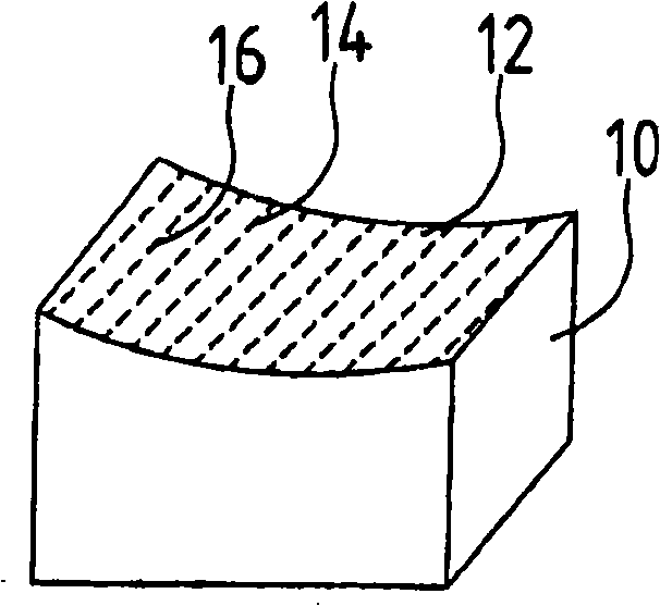
[0034] The drawing shows a schematic diagram of a carbon brush made of conventional materials, such as carbon graphite and / or natural graphite with synthetic resin as binder. The corresponding carbon brushes are pressed and preprocessed, if necessary, by grinding or sawing. In order to obtain the desired properties of the carbon brushes, especially with regard to running-in operation, laser processing is carried out. For example according to figure 1 The carbon brush 10 obtained in , shows that the working surface 12 of the carbon brush 10 is provided with holes 14, 16, which are formed by laser machining. In this case, the running surface 12 wears faster due to the bores 14 , 16 , with the result that a gentle running-in behavior is achieved, since the running surface 14 wears faster.

[0035] However, the holes 14 , 16 can also be used to receive an impregnating agent, which can thus be evenly distributed on the working surface 12 . Lubricant and / or abrasive materials can...


PUM


Abstract

The present invention relates to an electric sliding connect terminal such as carbon brushes, which is provides with a base body prepared with artificial graphite materials and by processes such as pressing, heat treatment and subsequent processing when necessary. The base body(10)of the sliding connect terminal is processed with laser for realizing a process with a high precision by a simple measure.

Description

technical field [0001] The invention relates to an electrical contact, such as a carbon brush, having a base body made of a carbon material, such as an artificial graphite material, and produced, for example, by pressing and heat treatment and possibly subsequent machining, as well as a tool for machining the electrical contact method. Background technique [0002] An electrical contact and a method for producing the electrical contact are described in DE-C-19821529. This relates to a wear-resistant electrical slider for a potentiometer and a method for producing the electrical slider. It is proposed to manufacture the pole plates for the production of the sliders, then to structure and separate the pole plates. A laser processing method is disclosed for processing the upstream stages of electrical contacts. [0003] For current collectors, for example, electrical contacts such as in particular carbon brushes or slides are used, which have the task of transmitting current...

Claims


Application Information

Patent Timeline
Patent Type & Authority Applications(China)
IPC IPC(8): H01R39/20H01R39/26H01R43/12
CPCH01R43/12H01R39/26
Inventor A·格哈特
Owner GERHARD PRAZISIONSPRESSTECHN
Why Eureka
Try Eureka