
Stack-press device

A pressure-bearing ring and mounting hole technology, which is applied in the field of lamination devices, can solve the problems of unable to produce stators, small construction space, and inability to carry out welding work, so as to achieve the effects of convenient welding, avoiding oil leakage, and facilitating installation

Active Publication Date: 2008-12-10
常州市华立液压润滑设备有限公司
View PDF1 Cites 4 Cited by
  • Summary
  • Abstract
  • Description
  • Claims
  • Application Information

AI Technical Summary

Problems solved by technology

[0005] According to the conventional thinking: use 24 oil cylinders arranged on the upper cover, and press from top to bottom through the pressure ring. Since the pressure to be applied is about 1600 tons, the upper cover must be very firm and thick. To ensure that the upper cover can withstand the bending moment during pressurization; the consequence of the structure of 24 oil cylinders on the thick upper cover is that the opening for welding the stator is very small, resulting in a large construction space. Very small, so welding work is not possible, so it is impossible to produce a qualified stator for large wind turbines

Method used


Image

  • Stack-press device
  • Stack-press device
  • Stack-press device

Examples


Embodiment 1

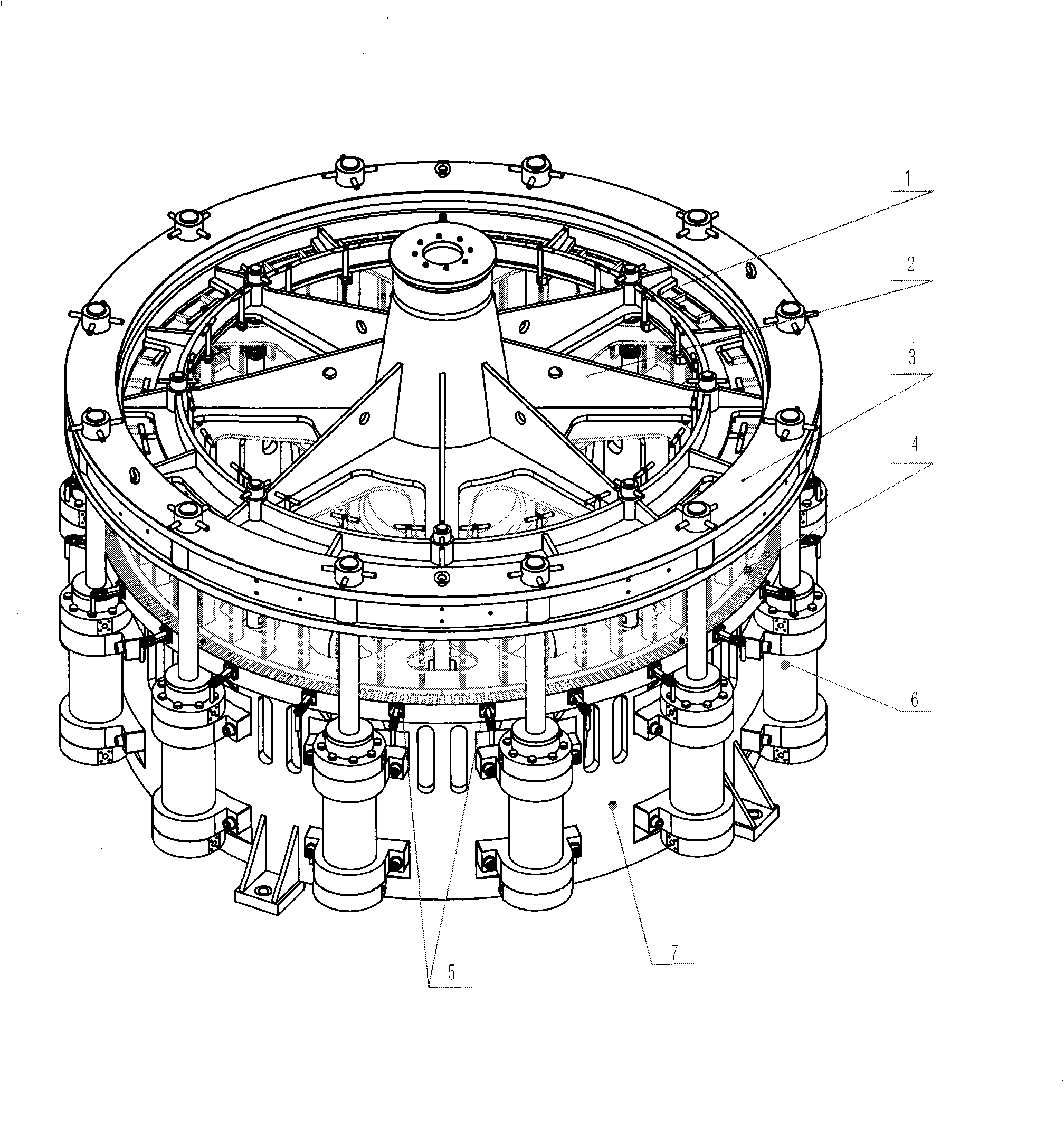
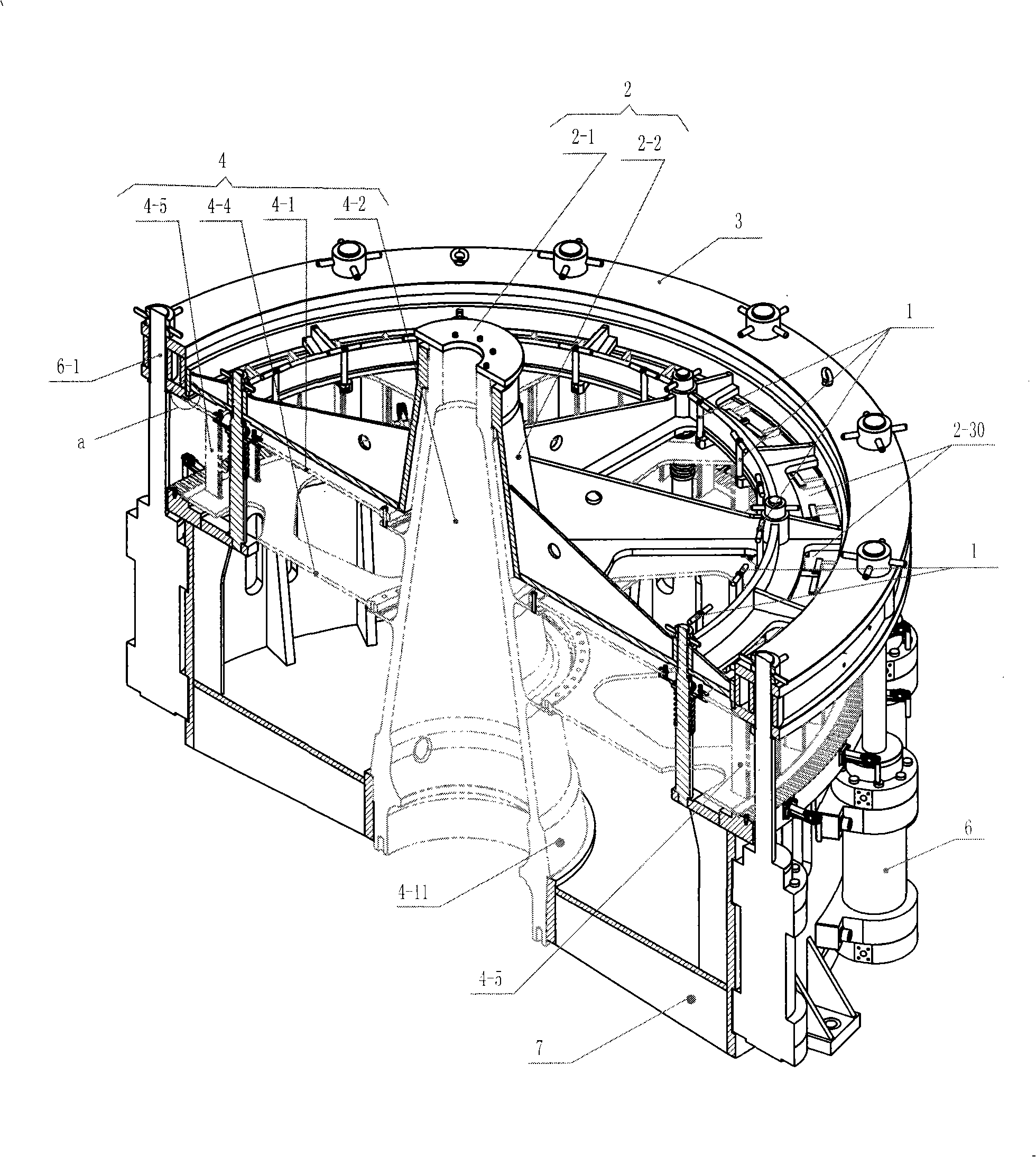
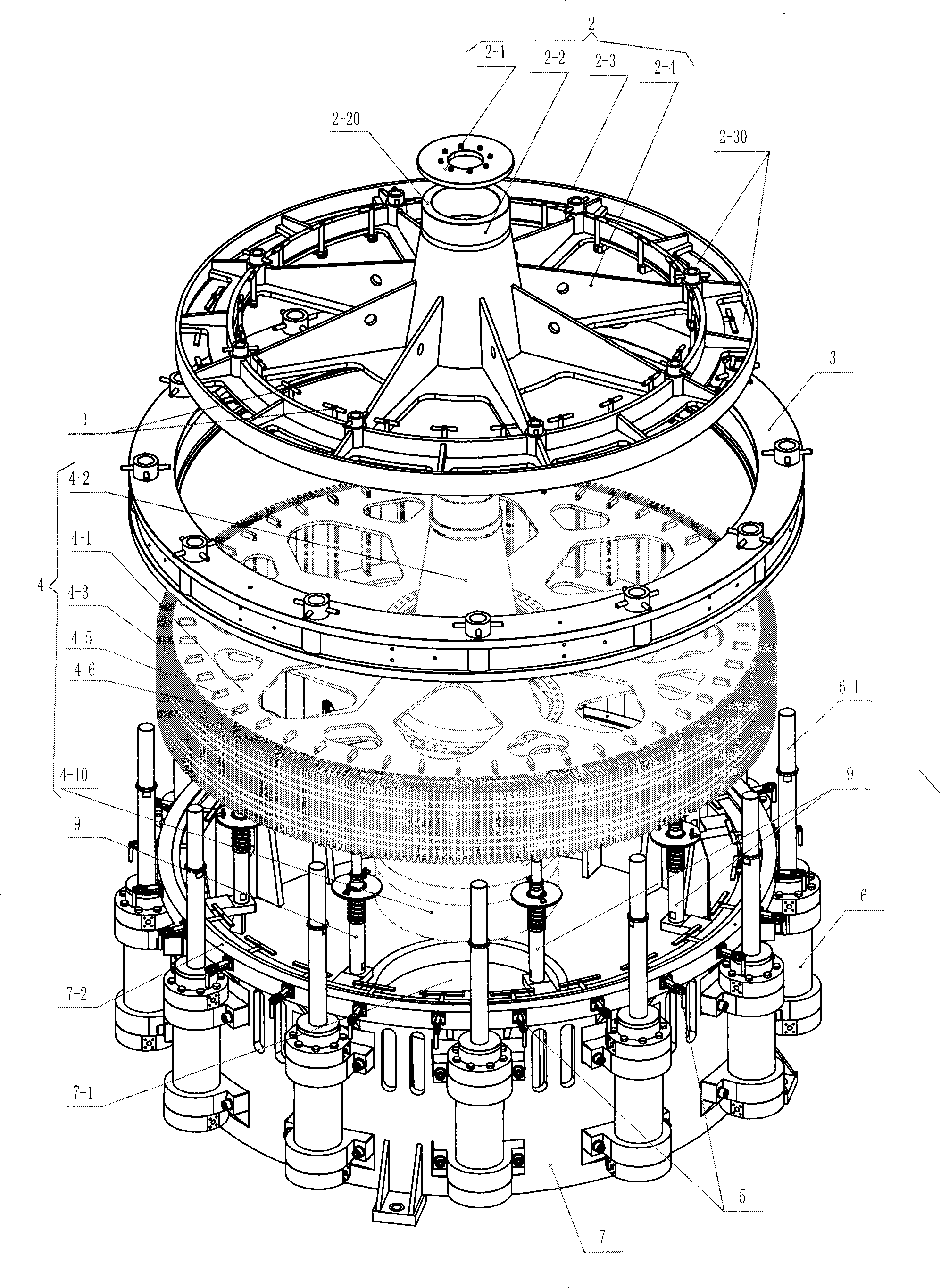
[0022] See Figure 1-3 , The laminating device of this embodiment includes: a base 7 , 12 pull-down oil cylinders 6 evenly distributed on the outer wall of the base 7 , a pressure bearing ring 3 and an upper cover 2 . Oil cylinder 6 is a heavy-duty oil cylinder.

[0023] When in use, the base 7 is provided with the main shaft 4-2 of the stator 4 to be laminated, and the main shaft 4-2 is provided with a disc-shaped front end plate 4-1 and a rear end plate 4-4 correspondingly arranged up and down. , the silicon steel sheet 4-3 of the stator 4 is arranged between the front end plate 4-1 and the rear end plate 4-4; the pressure ring 3 and the upper cover 2 are used to be arranged above the front end plate 4-1 of the stator 4 , and the upper cover 2 is located on the inner side of the pressure ring 3; 12 installation holes are evenly distributed on the pressure ring 3, the cylinder body of each oil cylinder 6 is fixed on the outer wall of the base 7, and the piston rod 6- 1 is f...


PUM


Abstract

In order to meet the requirements of laminating and welding coiled silicon steel sheets of a large-sized wind generator stator, the invention provides a laminating device, which includes: a base, a drop-down cylinder, a bearing ring and an upper cover; when used, the main shaft of a stator is inserted into a main shaft hole of the base, the main shaft is provided with front, rear end plates, the coiled silicon steel sheet is arranged between the front, rear end plates; the bearing ring and the upper cover are arranged above the front end plate, the upper cover is arranged on the inner side of the bearing ring and fixed on the upright post of the base; each cylinder is fixed on the base, the piston rod of the cylinder is fixedly connected with the bearing ring. When laminating, the piston rod of each cylinder pulls the bearing ring downwards. At the moment, the upper cover does not bear the laminating pressure, and only locates the stator pull rod on the stator, so the upper cover can be designed as a light cover, and a big enough opening for welding can be opened on the upper cover, without other shading objects, the staff can enter into the stator through the opening to weld.

Description

technical field [0001] The invention relates to a lamination device, in particular to a lamination device for integrally laminating stator silicon steel sheets of a large-scale wind power generator. Background technique [0002] In response to the national call for energy conservation and environmental protection, development and utilization of clean energy, the application of wind turbines is gradually becoming popular. For example: Chinese Patent Literature Publication No. CN200996357Y discloses a wind power generator, including wind blades, a generator, a rechargeable battery, an inverter controller and a chassis. [0003] According to the technical requirements of the wind turbine stator, the stator includes: the main shaft, the front end plate and the rear end plate set on the main shaft; A plurality of stator tie rods are evenly distributed on the inner peripheral wall of the front and rear end plates. There are tie rod installation holes corresponding to the stator t...

Claims


Application Information

Patent Timeline
Patent Type & Authority Applications(China)
IPC IPC(8): H02K15/02
CPCY02E10/72
Inventor 胡开平高超马瑞刘勇
Owner 常州市华立液压润滑设备有限公司
Learn More