Automatic expansion shaft

An automatic technology for expanding and tightening the shaft, which is applied in printing, rotary printing presses, printing presses, etc., can solve the problems of manual air feeding, and the air expansion shaft depends on the air source, etc., and achieves simple structure, easy operation, and reduced labor intensity. Effect

Inactive Publication Date: 2008-12-24
XIAN UNIV OF TECH
View PDF0 Cites 33 Cited by
  • Summary
  • Abstract
  • Description
  • Claims
  • Application Information

AI Technical Summary

Problems solved by technology

[0003] The purpose of the present invention is to provide an automatic expansion shaft, which solve...

Method used


Image

  • Automatic expansion shaft
  • Automatic expansion shaft
  • Automatic expansion shaft

Examples


Embodiment Construction

[0015] The present invention will be described in detail below in conjunction with the accompanying drawings and specific embodiments.

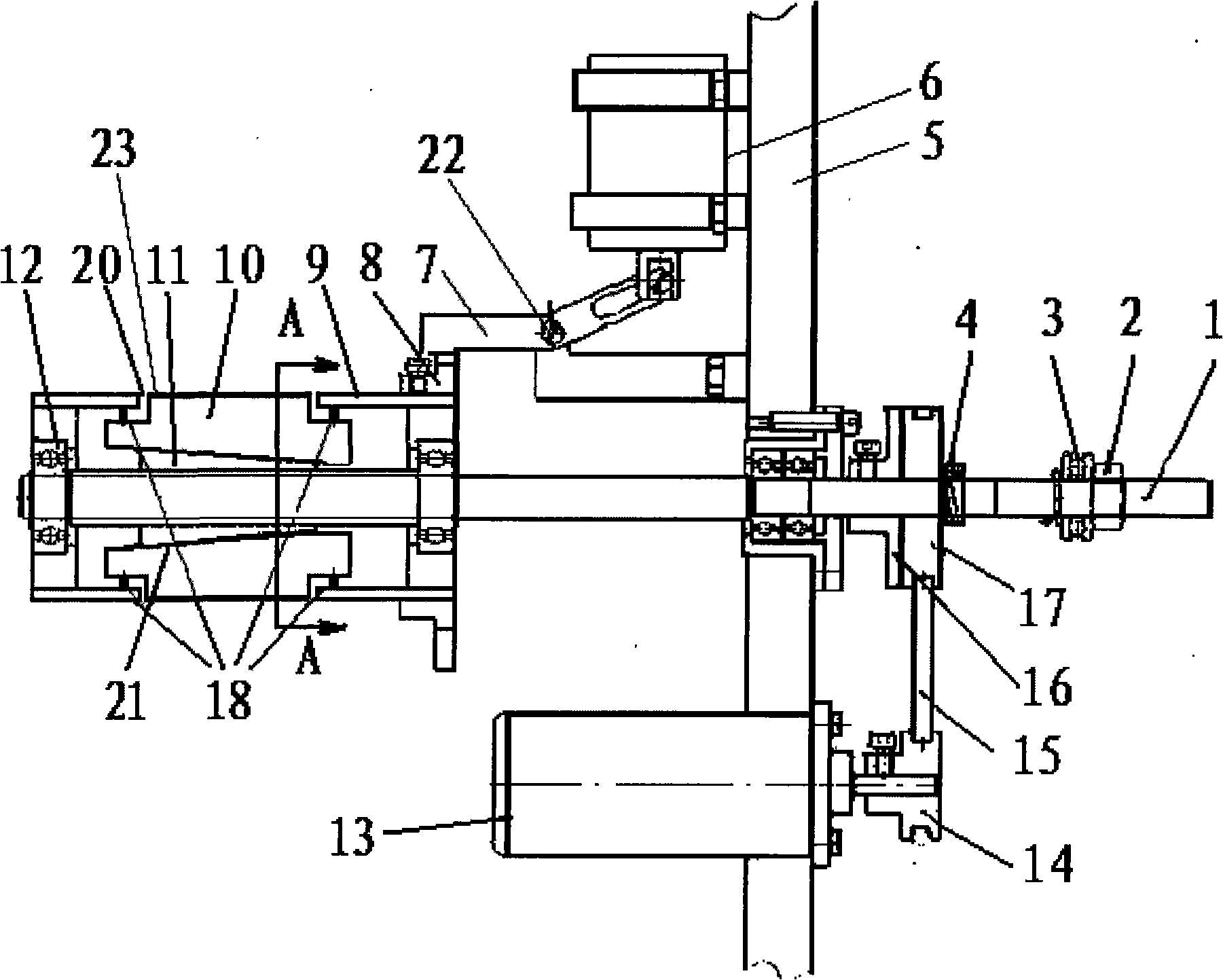
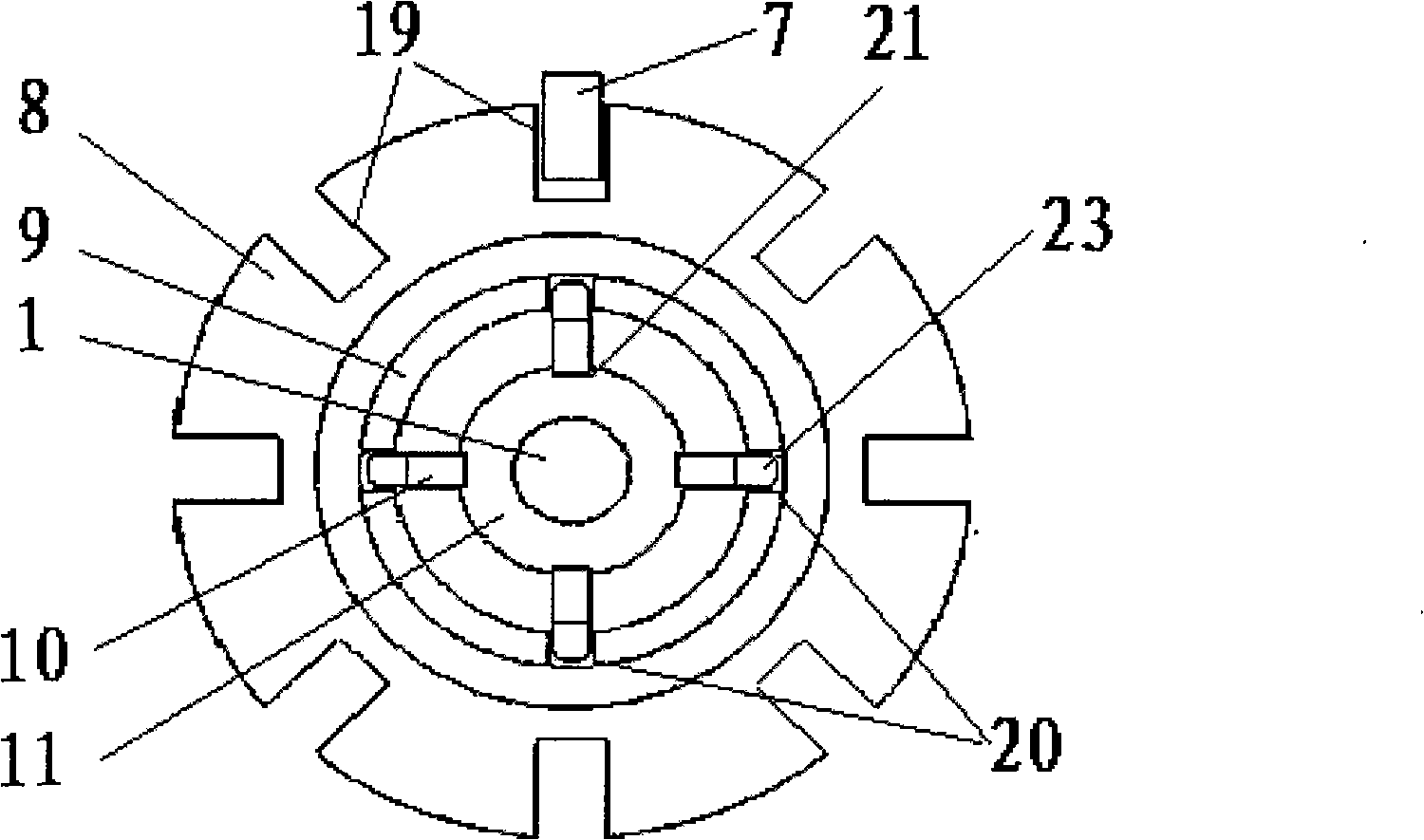
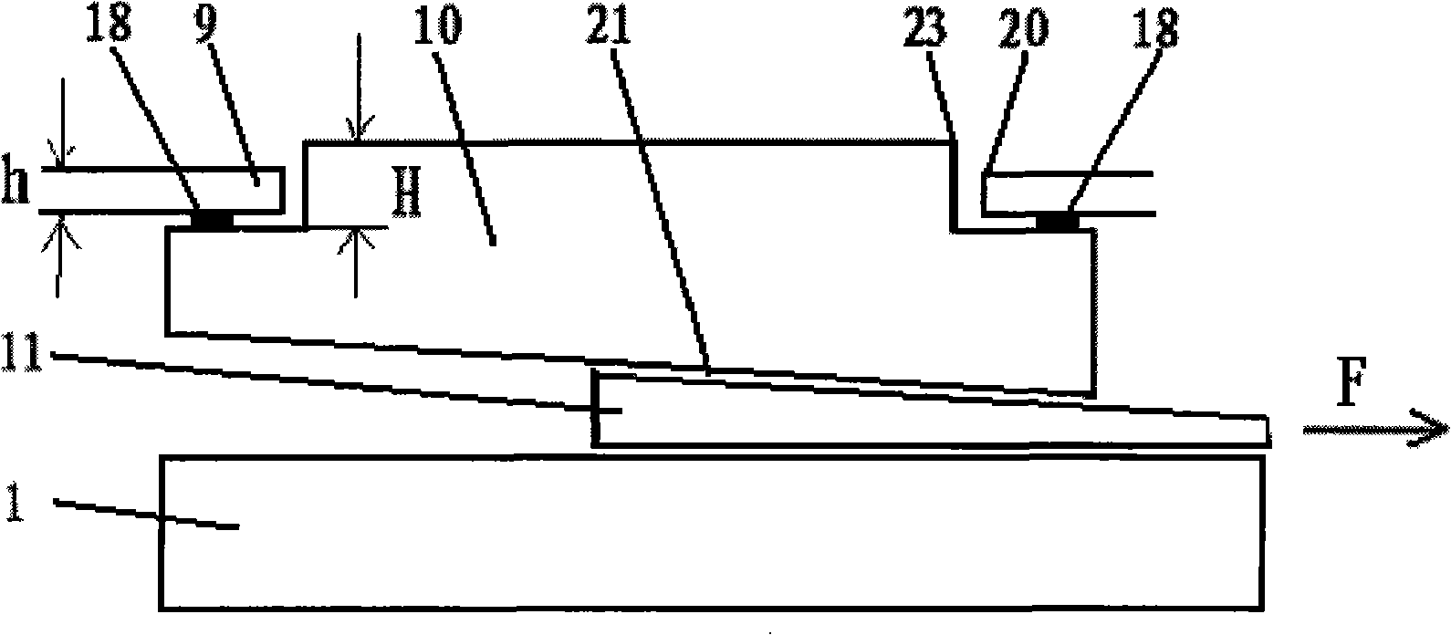
[0016] figure 1 It is a structural schematic diagram of the automatic tensioning shaft of the present invention. It includes a self-expanding part and a driving part, and the driving part is arranged at one end of the lead screw 1, that is, the transmission end, for realizing the rotation of the self-expanding shaft. The driving part includes a lead screw 1, the lead screw 1 is installed through the wallboard 5, the friction wheel 16 is coaxially fixedly installed on the lead screw 1, and a freely rotatable driven wheel 17 is coaxially installed on the lead screw 1, and the driven wheel 17 The compression spring 4 is in surface contact with the friction wheel 16 , and the driven wheel 17 is connected with the transmission wheel 14 of the DC motor 13 through the transmission belt 15 . A thrust bearing 3 and an adjustment nut 2 are installed ...


PUM


Abstract

The invention discloses an automatic expansion shaft which comprises a self-expansion part and a driving part. The self-expansion part comprises a sleeve. The circumference of the sleeve is symmetrically provided with a plurality of continuous grooves along axial direction. The sleeve is connected with a grooved sheave. A nut is arranged in the sleeve. The external circumference of the nut is an oblique cone plane. Sliding trays corresponding to the continuous grooves are arranged on the oblique cone plane of the nut. An expansion flake is arranged on every sliding tray. The external end surface of the expansion flake towards the external circumference is a lug boss which passes through the continuous grooves. The expansion flake is connected with the inner wall of the sleeve through a spring. The grooved sheave of the self-expansion part is connected with a positioning plate in a switching way. The positioning plate is connected with an electromagnetic valve. The electromagnetic valve and a DC electric machine are all connected with a control system. The automatic expansion shaft has the advantages of simple structure and using reliability, uses an electric actuator for replacing the manual ballooning operation and saves a compressed air source unit, thereby realizing the total automation from paper rolling to loading and unloading.

Description

technical field [0001] The invention belongs to the technical field of printing machinery and equipment, and relates to a paper cylinder installation device in printing and papermaking equipment, in particular to an automatic tensioning shaft. Background technique [0002] For web-type printing machines, the installation and fixing of the paper tube is unavoidable. Present printing machines generally adopt the method of installing the paper tube on the shaft, and then press it with a pressure sleeve to fix the paper tube. This method is labor-intensive and low in efficiency; some advanced models and foreign roll printing machines mostly use air expansion shafts to fix the paper tube, which reduces the labor intensity of workers to a certain extent and improves work efficiency, but There are still the following disadvantages: one is that the air shaft needs an air source; the other is that it is difficult to realize automatic operation and the work efficiency is low because i...

Claims


Application Information

Patent Timeline
IPC IPC(8): B41F13/03B65H16/00B65H16/02B65H19/10B65H18/10B65H18/02B65H19/22B65H75/10B65H75/24
Inventor 徐宏伟
Owner XIAN UNIV OF TECH
Why Eureka
Try Eureka