Vehicle body floor structure

A body floor and floor technology, applied in the direction of upper structure, vehicle parts, upper structure sub-assembly, etc., can solve the problems of lowering the floor frame 224, increasing weight, difficult aerodynamic performance, etc., to enhance aerodynamic performance and reduce weight , Increase the effect of internal space

Active Publication Date: 2008-12-24
HONDA MOTOR CO LTD
View PDF2 Cites 32 Cited by
  • Summary
  • Abstract
  • Description
  • Claims
  • Application Information

AI Technical Summary

Problems solved by technology

[0007] However, if the interior space of the vehicle is to be increased, the body floor structure disclosed in the 3434199 publication will encounter the problem that the height of the floor frame 224 has to be lowered, thereby reducing the height of the vehicle (from the ground)
Furthermore, since the forwardly extending left and right reinforcement members 226 and reinforcement gussets 227 are provided on the left and right sides of the vehicle floor, the weight of the disclosed vehicle body floor structure would undesirably increase to a considerable to a great extent
In addition, since the airflow (traveling air) flowing under the floor panel 223 is disturbed by the floor frame 224 during vehicle travel, it is difficult to obtain enhanced aerodynamic performance.

Method used


Image

  • Vehicle body floor structure
  • Vehicle body floor structure
  • Vehicle body floor structure

Examples


Embodiment Construction

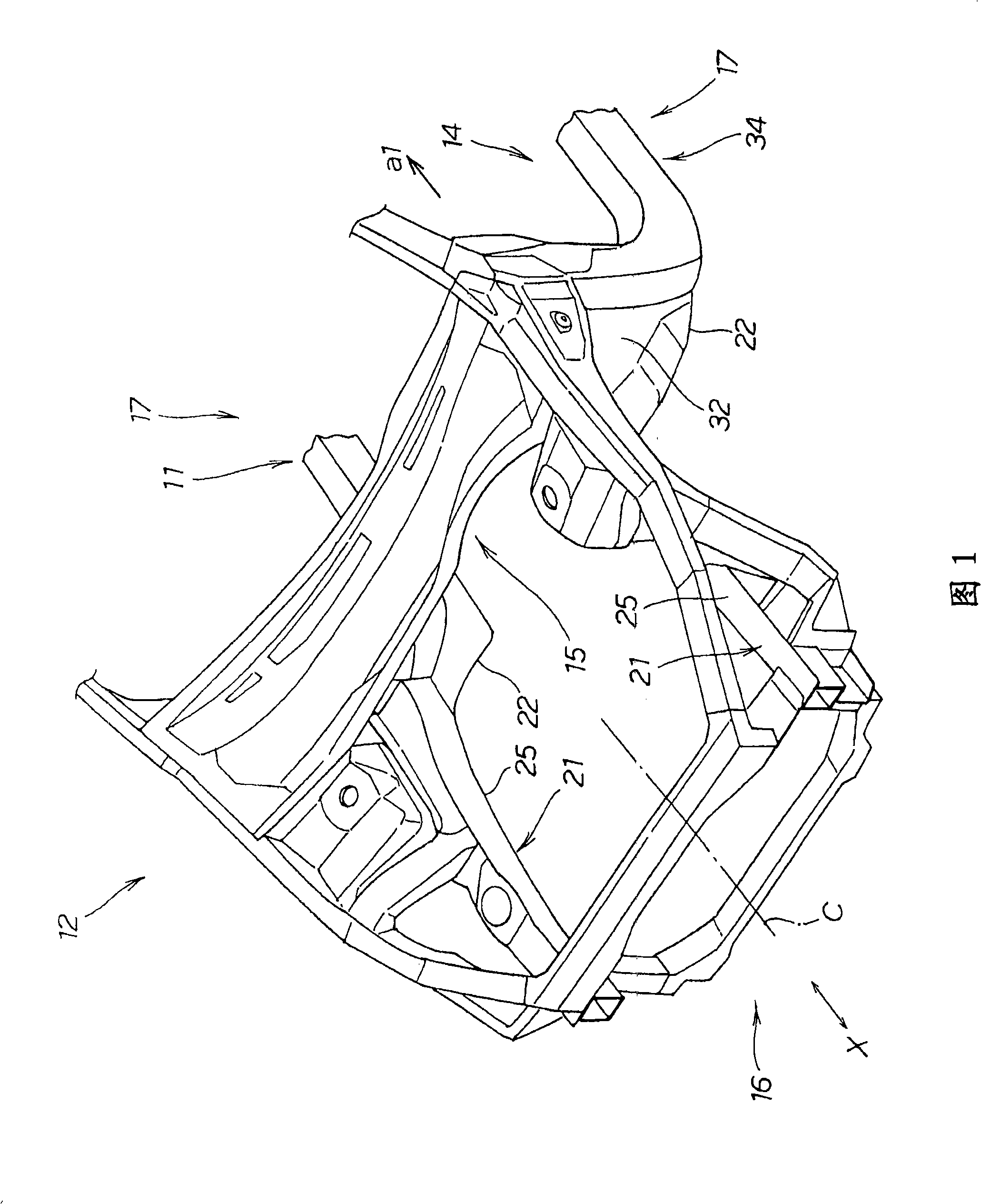
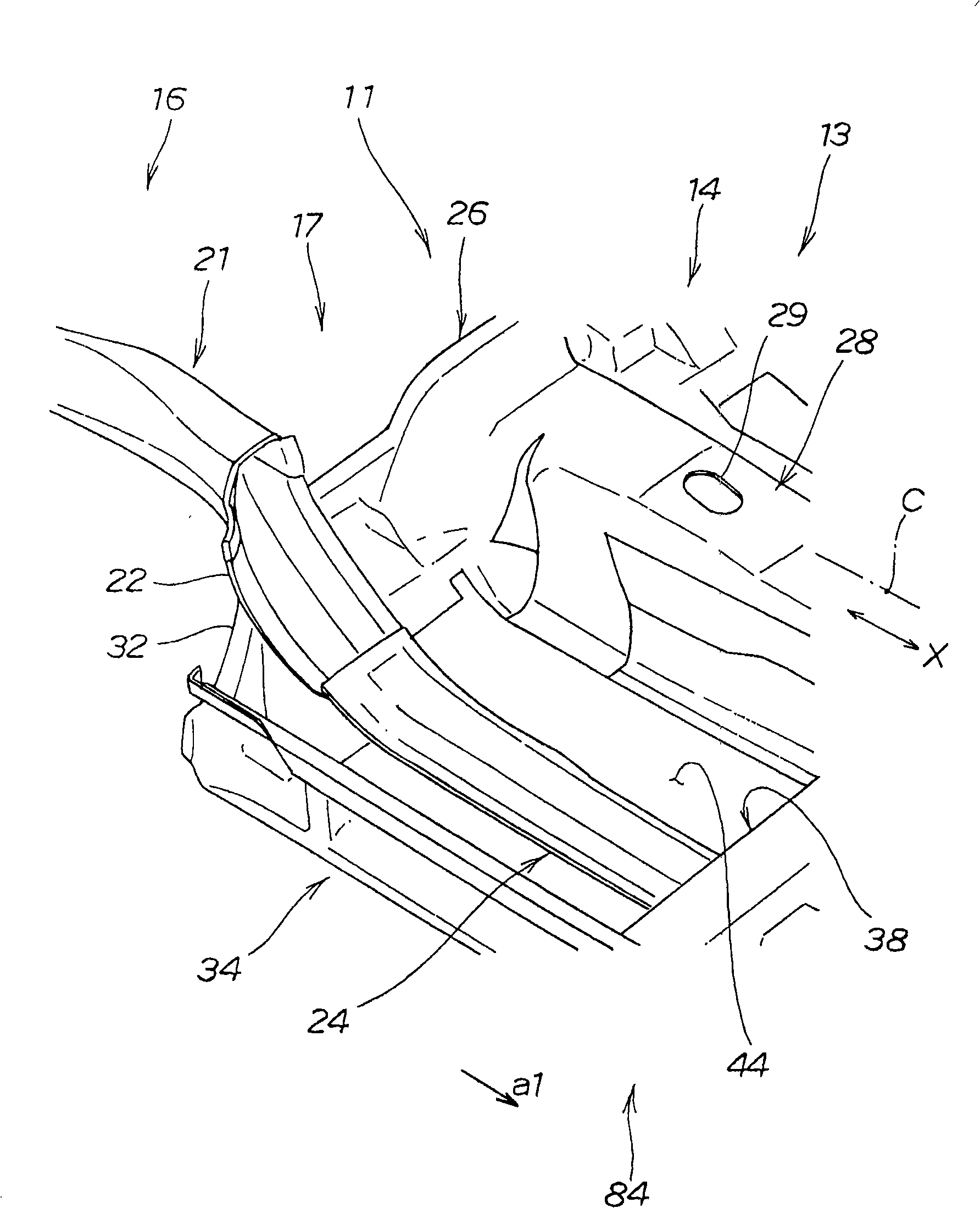
[0040] Referring now to Figure 1 and figure 2 , wherein, FIG. 1 is a perspective view of a front body connected to a vehicle body floor structure according to a first embodiment of the present invention, figure 2 is a perspective view of the front floor frame attached to the body floor structure.

[0041] A vehicle body floor structure 11 is used in a floor body 14 constituting a floor of a compartment 13 of a vehicle 12; the vehicle body floor structure 11 will be discussed in detail later.

[0042] The vehicle 12 includes: a floor main body 14 constituting a floor; a left main body and a right main body 17 constituting the side walls of the compartment 13; a front main body 16 provided at the front of the compartment 13; The compartment 13 is divided by a wall. The left and right side bodies 17 include left side sills 34 and right side sills 37 ( FIG. 3 ), which are connected to the left side of the floor body 14 . and on the right side.

[0043] The front main body 16...


PUM


Abstract

Vehicle body floor structure (11) includes: a floor panel (44); a floor cross member (38) provided on the floor panel and joined to left and side sills (34, 37); and left and right front floor frames (24) provided on the floor panel and extending from a dashboard cross member to a substantial middle region of the floor panel through a recessed portion (93) of the floor cross member. The left and right front floor frames each have a rear section (48) located rearwardly of the floor cross member, and these rear sections are bent outwardly to be joined to the left and right side sills, respectively. Each of the front floor frames (24) may be provided on the upper surface of a downwardly concaved floor section (67) of the floor panel and extend between the concaved floor section and the floor cross member.

Description

technical field [0001] The present invention relates to a vehicle body floor structure capable of properly receiving a lateral or side impact impact (ie, an impact due to a side impact of a vehicle). The present invention also relates to a vehicle body floor structure capable of properly receiving the impact of a frontal collision. Background technique [0002] A conventionally known floor structure of a vehicle body has a function of coping with the impact of a side collision, and is provided with a floor cross member which is provided under the front seats and extends in the left-right or width direction of the vehicle body, for example, as described in Japanese Patent Application Laid-Open Hei. As disclosed in No. 2005-119492A. [0003] Figure 16A and 16B is a view illustrating a conventional vehicle body floor structure disclosed in Publication No. 2005-119492. The disclosed vehicle body floor structure 201 includes: a left side sill and a right side sill provided on...

Claims


Application Information

Patent Timeline
Patent Type & Authority Applications(China)
IPC IPC(8): B62D25/20
Inventor 阿部佳朗小野田康信鸟羽良幸
Owner HONDA MOTOR CO LTD
Why Eureka
Try Eureka