Induction motor drive unit, motor drive system, and elevating system
A technology of induction motor and driving device, applied in the field of lifting system, can solve the problem of unnecessary consideration of deceleration of induction motor or stop processing slip frequency and other problems
- Summary
- Abstract
- Description
- Claims
- Application Information
AI Technical Summary
Problems solved by technology
Method used
Image


Examples
no. 1 Embodiment approach
[0026] As shown in Equation (1), when using lifting equipment such as a crane to hoist the cargo at an acceleration α, the required torque τm depends on the acceleration α and the weight m·g of the cargo (cargo). In addition, in formula (1), the cargo is hoisted by a pulley with radius r, J is the total moment of inertia including the motor or mechanical system (pulley, etc.), ω is the rotation speed of the motor, m is the mass of the cargo, and g is acceleration of gravity.
[0027] M·α·r=J·dω / dt=τm-m·g·r (1)
[0028] At this time, the maximum value of torque τm is determined by the capacity of the motor. When m·g·r is large, the acceleration α of formula (1) is negative or zero, and the cargo cannot be lifted. Furthermore, even if the acceleration α is positive, if the velocity change rate dω * / dt ratio (maximum torque τm max -m·g·r) / J is large, the motor cannot follow the instruction and the hoisting fails.
[0029] FIG. 1 is a configuration diagram of a motor drive sy...
no. 2 Embodiment approach
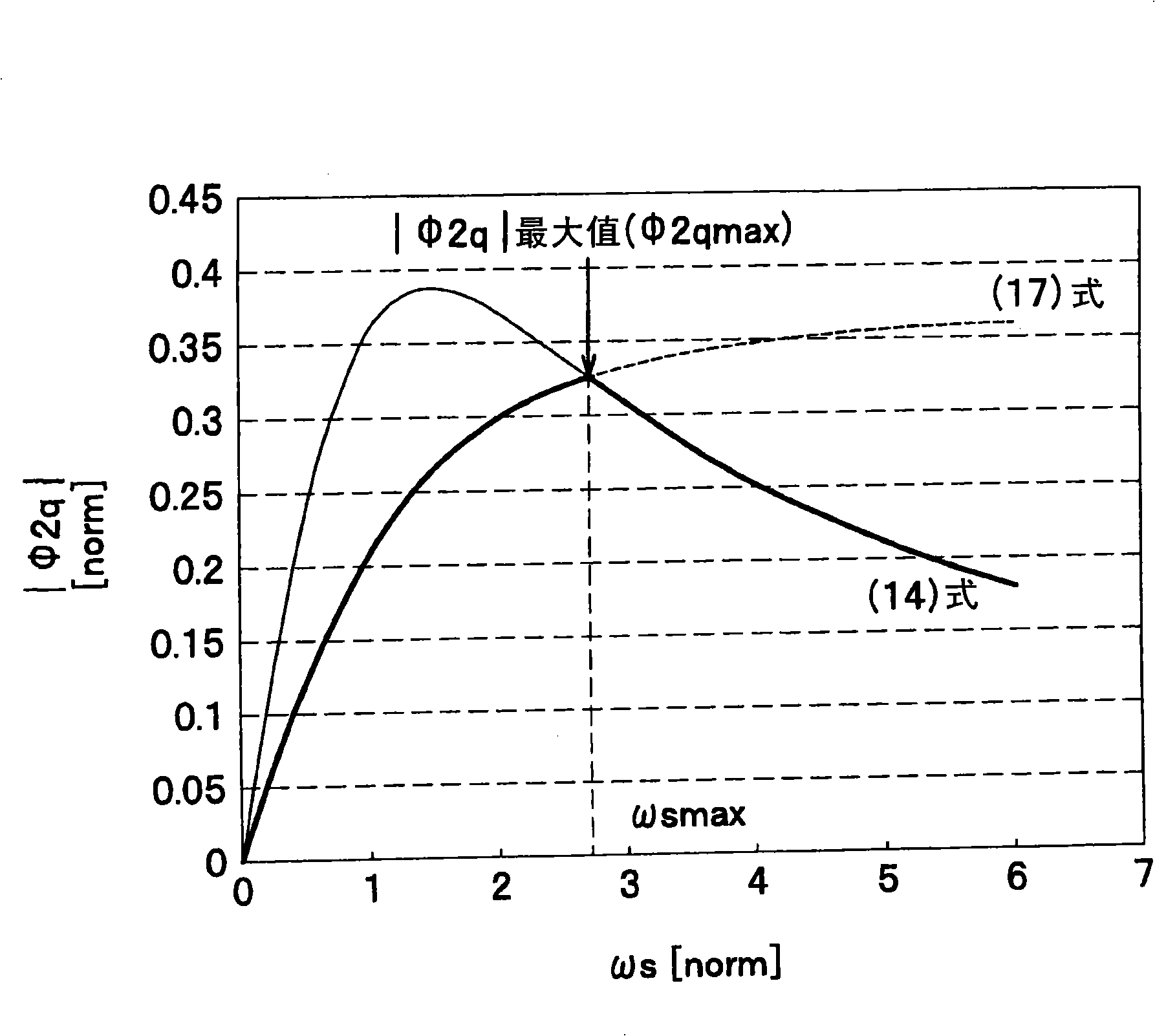
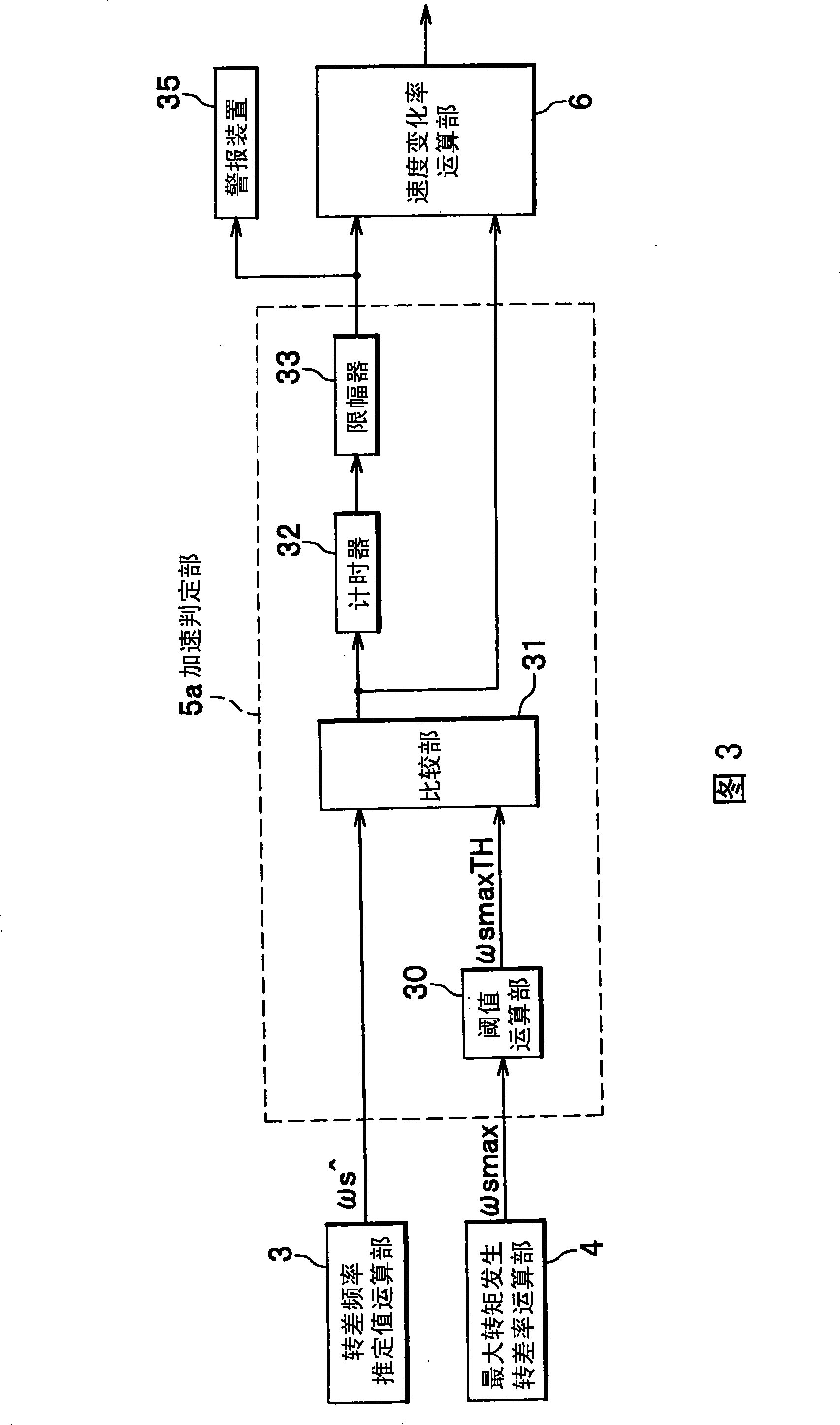
[0084] In the first embodiment, the occurrence of the maximum torque is detected based on the slip frequency ωs, but if figure 2 As shown, the determination that the slip frequency ωs exceeds ωsmax can also be determined based on the secondary side q-axis magnetic flux φ2q. As shown in FIG. 4 , the acceleration determination unit 5b of the second embodiment corresponds to the acceleration determination unit 5 ( FIG. 1 ), and includes a threshold calculation unit 42 and a comparison unit 43, and inputs the φq estimation calculation unit 40 as a q-axis magnetic flux calculation unit. and the output signal of the maximum torque generation φq calculation unit 41 as the maximum torque generation q-axis magnetic flux calculation unit.
[0085] A q-axis magnetic flux estimated value φ2q^ corresponding to ωs^ is calculated in the φq estimation calculation unit 40 , and a q-axis magnetic flux φ2qmax corresponding to ωsmax is calculated in the maximum torque generation φq calculation un...
no. 3 Embodiment approach
[0088] Differences between the third embodiment and the other embodiments will be described.
[0089] The acceleration determination unit 5c shown in FIG. 5 corresponds to the acceleration determination unit 5 (FIG. 1), but the q-axis magnetic flux estimation value φ2q^ may be calculated in the q-axis magnetic flux calculation unit, that is, the φq estimation calculation unit 40 instead. ωs^, in the maximum torque generation q-axis magnetic flux calculation unit 41 that is the maximum torque generation φq calculation unit, the q-axis magnetic flux φ2qmax corresponding to ωsmax is calculated.
[0090] The comparison unit 53 outputs a signal when φ2q^ is smaller than the output φ2qmaxTH of the threshold calculation unit 42 . The timer 54 outputs the time from the time when the above-mentioned signal was received. That is, when the state of 0>φ2qmaxTH>φ2q^ continues and the output of the timer 54 exceeds a predetermined threshold, the acceleration determination unit 5c determine...
PUM
 Abstract
Description
Claims
Application Information
 - Generate Ideas
- Intellectual Property
- Life Sciences
- Materials
- Tech Scout
- Unparalleled Data Quality
- Higher Quality Content
- 60% Fewer Hallucinations
Browse by: Latest US Patents, China's latest patents, Technical Efficacy Thesaurus, Application Domain, Technology Topic, Popular Technical Reports.
© 2025 PatSnap. All rights reserved.Legal|Privacy policy|Modern Slavery Act Transparency Statement|Sitemap|About US| Contact US: help@patsnap.com