
Integrated hub motor driving unit

A hub motor and drive unit technology, which is applied in the direction of gear transmission, brakes, mechanical equipment, etc., can solve the problems of the mass of the electric wheel assembly, the noise of the electric wheel assembly is too large, and the wheel power is insufficient, so as to achieve a compact structure , Improving the power of the vehicle and the effect of light weight

Active Publication Date: 2017-12-19
DONGFENG MOTOR CORP HUBEI
View PDF6 Cites 31 Cited by
  • Summary
  • Abstract
  • Description
  • Claims
  • Application Information

AI Technical Summary

Problems solved by technology

[0003] In the Chinese invention patent CN104590001A, an integrated in-wheel motor drive unit is disclosed, which applies the drive motor, two-stage planetary gear reduction mechanism, brake disc, brake, etc. Traditional automotive components such as transmissions and drive shafts have greatly reduced the weight of the vehicle and improved transmission efficiency; and achieved high torque output through the two-stage planetary gear reduction mechanism; however, this technical solution uses two-stage planetary gears The deceleration mechanism requires a long drive motor with large width and small diameter to facilitate the installation of the two-stage planetary gear reducer and achieve stable power output. Due to the large width and small diameter of the drive motor, the rim of the corresponding automobile wheel It will also become larger, which will cause the mass of the electric wheel assembly to increase and increase the energy consumption of the wheel. At the same time, due to the small diameter of the two-stage planetary gear reduction mechanism, the corresponding torque will decrease. Insufficient situation; at the same time, due to the transmission pair structure of the two-stage planetary gear reduction mechanism, the electric wheel assembly has the disadvantages of high noise, poor sealing scheme, and difficult disassembly and assembly.

Method used


Image

  • Integrated hub motor driving unit
  • Integrated hub motor driving unit
  • Integrated hub motor driving unit

Examples


Embodiment Construction

[0029] In order to make the object, technical solution and advantages of the present invention clearer, the present invention will be further described in detail below in conjunction with the accompanying drawings and embodiments. It should be understood that the specific embodiments described here are only used to explain the present invention, not to limit the present invention.

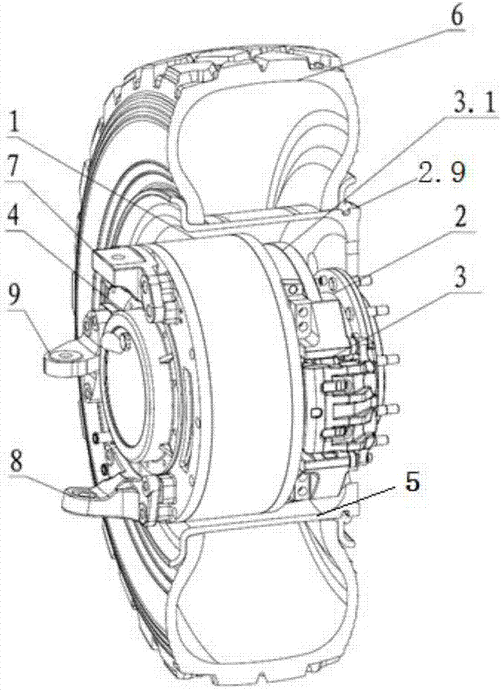
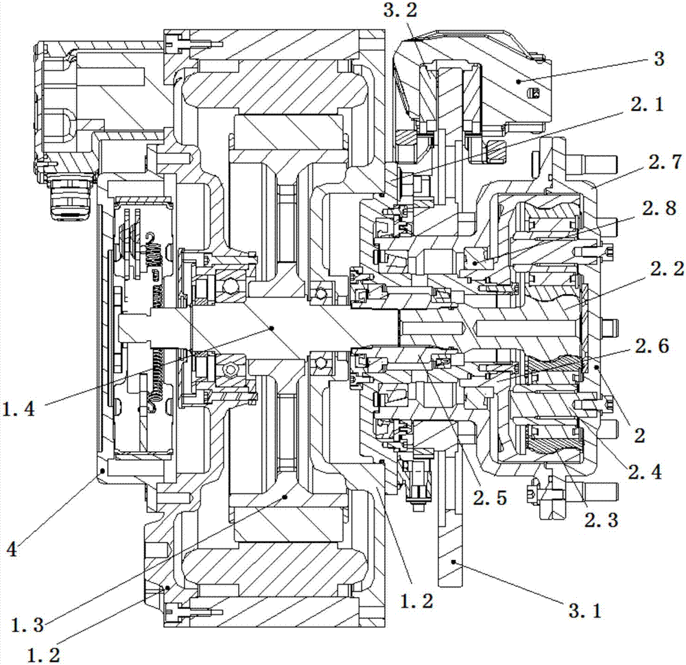
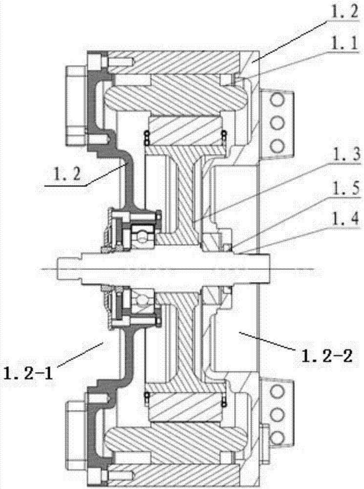
[0030]It can be seen from the schematic structural diagram of an integrated hub motor drive unit shown in the specification that an integrated hub motor drive unit of the present invention mainly includes a drive motor 1, a planetary reduction mechanism 2, a service brake 3 including a drive brake Moving disc 3.1, brake caliper 3.2 and caliper mount 3.3, parking brake 4, rim 5, tire 6, upper joint arm 7, lower joint arm 8, steering knuckle arm 9, etc. The motor 1 is a permanent magnet synchronous disc motor, which is arranged inside the rim 5, the stator 1.1 is fixed to the motor housing 1.2, the i...


PUM


Abstract

The invention discloses an integrated hub motor driving unit which comprises a driving motor arranged inside a rim. A motor shaft of the driving motor is supported on a motor shell through a motor bearing; one side of the motor shaft is connected with a parking brake, and the other side of the motor shaft is connected with a driving brake through a planetary deceleration mechanism; the planetary deceleration mechanism is a first-stage planetary wheel mechanism; and the input end of the planetary deceleration mechanism is connected with the motor shaft, and the output end of the planetary deceleration mechanism is connected with the rim and a brake disc of the driving brake. The integrated hub motor driving unit is simple in structure and convenient to use and replace, the functions of driving, braking and supporting are achieved at the same time, all the components are integrated in a wheel and compact in structure, the parking brake with the smaller capacity is used, and thus the excellent performance of the short braking distance and the high parking slope is achieved.

Description

technical field [0001] The invention relates to an in-wheel motor drive unit, which belongs to the technical field of drive unit components of a hybrid electric vehicle, in particular to an in-wheel motor drive unit integrating the functions of driving, deceleration, braking and support. Background technique [0002] With the development of new energy vehicle technology, there are more and more drive schemes for hybrid and electric vehicles. Hybrid and pure electric vehicles that are common in the market mainly replace the engine with a motor or add a motor and battery, while the form of power transmission devices such as gearboxes and drive shafts are still retained. Compared with traditional models, the weight of the vehicle has not been reduced, and the technical complexity has increased . Improving the mileage of electric vehicles is the goal that electric vehicles have been pursuing. Reducing vehicle curb weight and simplifying the transmission structure are important ...

Claims


Application Information

Patent Timeline
Patent Type & Authority Applications(China)
IPC IPC(8): B60K7/00B60K17/12B60T1/06F16H3/44
CPCB60K7/00B60K17/12B60T1/06F16H3/44
Inventor 蔡未末李进伟汪振晓薛琼
Owner DONGFENG MOTOR CORP HUBEI
Learn More