Method for direct communication between optical network units and passive optical network system

A technology of passive optical network and optical network unit, applied in the direction of optical multiplexing system, multiplexing communication, multiplexing system selection device, etc. Support P2P business efficiency is not high

Inactive Publication Date: 2008-12-24
BEIJING UNIV OF POSTS & TELECOMM
View PDF0 Cites 11 Cited by
  • Summary
  • Abstract
  • Description
  • Claims
  • Application Information

AI Technical Summary

Problems solved by technology

With the popularity of peer-to-peer services (P2P, Peerto Peer), the proportion of communication traffic between ONUs in the total network bandwidth is also increasing, and the point-to-multipoint tree-shaped PON of the master-slave structure shows support Weaknesses such as low efficiency of P2P business, circuitous communication, repeated occupation of backbone MAN network resources, etc.

Method used


Image

  • Method for direct communication between optical network units and passive optical network system
  • Method for direct communication between optical network units and passive optical network system
  • Method for direct communication between optical network units and passive optical network system

Examples


Embodiment 1

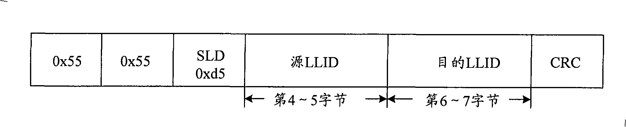
[0062] First introduce the preamble structure of the Ethernet frame that this embodiment adopts, as figure 1 As shown, in this embodiment, the 4th to 5th bytes of the preamble carry the source LLID, that is, the LLID of the source ONU; the 6th to 7th bytes carry the destination LLID, that is, the LLID of the destination ONU.

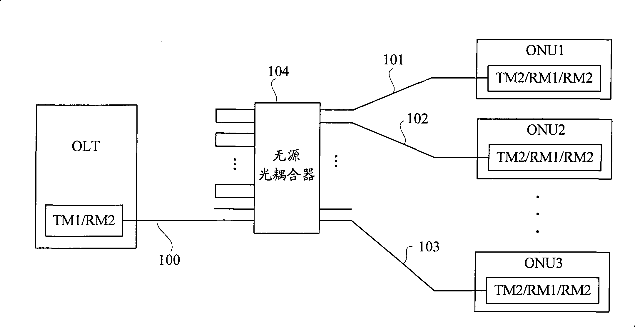
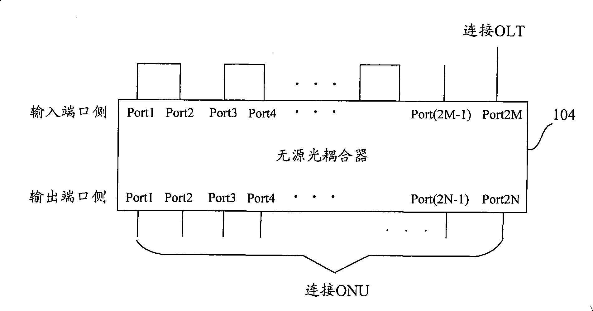
[0063] figure 2 It is a schematic structural diagram of the passive optical network system described in this embodiment. Such as figure 2 As shown, the OLT is provided with a set of optical transmitting and receiving modules TM1 / RM2, which are connected to the input port of the passive optical coupler through the main optical fiber 100 . The branch ratio of the passive optical coupler 104 (ie, the ratio of the input port to the output port) is 2M:2N, where M and N are both integers and M=N≧2. Each ONU is equipped with a set of optical transmitting and receiving modules TM2 / RM2 / RM1, which are respectively connected to the output port of the passive o...

Embodiment 2

[0100] Such as Image 6 As shown, the passive optical network system described in this embodiment includes an OLT, two passive optical couplers with a branch ratio of 2M:2N, and multiple ONUs. In this embodiment, the OLT is provided with two sets of optical transmitting and receiving modules TM1 / RM2, and each ONU is respectively provided with two sets of optical transmitting and receiving modules TM2 / RM2 / RM1. Please refer to Figure 7 , the first input port of the passive optical coupler 601 is connected to a set of optical transmitting and receiving modules of the optical line terminal OLT, and the first input port of the passive optical coupler 602 is connected to another set of optical transmitting and receiving modules of the optical line terminal OLT module, the remaining input ports of the passive optical coupler 601 are connected with the remaining input ports of the passive optical coupler 602 in pairs.

[0101] In this embodiment, each ONU specifically may include: ...


PUM


Abstract

The invention provides a method for direct communication between optical network units and a passive optical network system. The method comprises the following steps: a first ONU transmits a first data frame carrying an objective LLID and a source LLID to a passive optical coupler; first data frames received on an output port of the passive optical coupler are distributed on each input port thereof through the passive optical coupler, and passes through at least two input ports which are butted against each other; a first data frame ring returns to each input port of the passive optical coupler; each ONU in the passive optical network system receives the first data frame, and judges whether the objective LLID in the first data frame belongs to one of a main LLID and a broadcasting LLID; if the objective LLID belongs to one of the main LLID and the broadcasting LLID, the first data frame is processed; otherwise, the first data frame is discarded. According to the method, the direct communication between the ONUs can be realized; therefore, the service bearing efficiency is enhanced, the time delay between the ONUs is reduced, and the burden on a backbone network is lightened.

Description

technical field [0001] The invention relates to the technical field of optical communication, in particular to a method for direct communication between optical network units and a passive optical network system. Background technique [0002] Driven by the strong demand for broadband services such as high-speed Internet access, video, and Ethernet private lines, Passive Optical Network (PON) is characterized by its high bandwidth, low cost, suitable for multicast service transmission, easy maintenance, and high reliability. And other advantages become the mainstream technology of optical access network. The PON system connects the optical line terminal (OLT, Optical Line Terminal) and the optical network unit (ONU, Optical Net Unit) through the optical distribution network (ODN, Optical Distribution Network). / Combiner, that is, the backbone optical fiber between passive optical couplers can be shared, and then the optical power is divided and combined through the optical c...

Claims


Application Information

Patent Timeline
Patent Type & Authority Applications(China)
IPC IPC(8): H04Q11/00H04J14/00
Inventor 陈雪张治国王震王立芊
Owner BEIJING UNIV OF POSTS & TELECOMM
Why Eureka
Try Eureka