A gravity separator, and a method for separating a mixture containing water, oil, and gas

A technology for gravity separators and mixtures, applied in separation methods, chemical instruments and methods, solid separation, etc., can solve the problems of complex separators, high maintenance, clogging capacity, etc., and achieve maintenance costs free, reliable design, and simple design. Effect

Inactive Publication Date: 2008-12-24
SHCLUMBERGER NORGE AS
View PDF5 Cites 6 Cited by
  • Summary
  • Abstract
  • Description
  • Claims
  • Application Information

AI Technical Summary

Problems solved by technology

Using a coalescer riser with a filter or using a grid plate complicates the separator and risks clogging with loss of capacity
These prior art designs also require a high degree of maintenance work

Method used


Image

  • A gravity separator, and a method for separating a mixture containing water, oil, and gas
  • A gravity separator, and a method for separating a mixture containing water, oil, and gas

Examples


Embodiment Construction

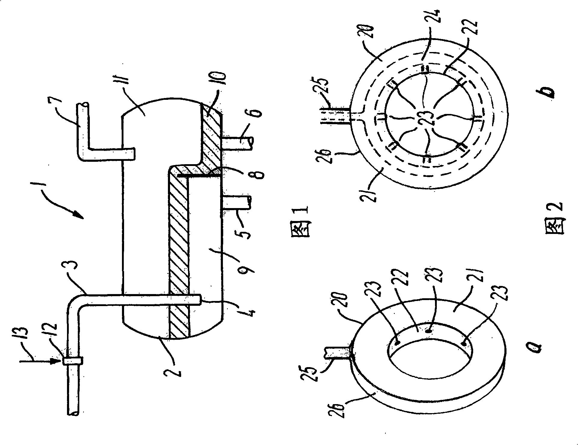
[0023] Referring to FIG. 1 , there is shown a gravity separator 1 having a vessel 2 with an inlet pipe 3 having a vessel inlet 4 inside the vessel 2 . The inflow of the fluid mixture through the inlet 4 spreads itself freely into the container where gravity acts on the ingredients in the mixture. The container 2 is also equipped with a water outlet 5 , an oil outlet 6 and a gas outlet 7 . Inside the vessel 2 there is a weir 8 which serves to separate the water phase 9 from the oil phase 10 . The gas phase 11 is collected at a position in the space above the water phase 9 and the oil phase 10 .

[0024] In the introduction pipe 3 of the container 2 there are installed injection means 12 for injecting gas in the form of a nozzle arrangement. A gaseous medium is fed to the nozzle arrangement via line 13 . In this way, a gaseous medium is sprayed into the mixture in the introduction pipe 3 before the mixture containing water, oil and gas enters the container 2 via the container...


PUM


Abstract

A gravity separator comprises a vessel within which a mixture containing water, oil, and gas can separate under gravity to form vertically discrete oil and water layers and a gas phase. An inlet duct communicates with a vessel entrance for the mixture containing water, oil, and gas. The inlet duct of the gravity separator comprises injector means injecting a gaseous medium in a volume in the range of 0.01-1.9 Sm<3> gaseous medium per 1m<3> mixture into the mixture containing water, oil, and gas.

Description

technical field [0001] The present invention relates to a gravity separator, primarily of the type in which a mixture containing water, oil and gas flowing from an oil well is separated in a separator vessel into discrete vertical Vertically separated layers of water, oil and gas for subsequent extraction from the container through the water outlet, the oil outlet and the gas outlet respectively. Background technique [0002] Gravity separators have been known for decades and have been used in the oil industry in various embodiments, some of which are quite complex, including multiple static mixers and cyclones. Examples of known types of gravity separators are known, for example, from GB1327991 and WO99 / 25454. US Patent No. 5080802 discloses an air flotation separator having ejectors that draw gas into the incoming fluid. The eductor recirculates the gas collected at the very top of the vessel to the incoming fluid. The separator is provided with a coalescer riser substa...

Claims


Application Information

Patent Timeline
Patent Type & Authority Applications(China)
IPC IPC(8): B01D17/00B01D17/025B01D17/035E21B43/40E21B43/34B03D1/14
CPCB01D17/00B01D19/0005C02F1/24C02F1/40C02F1/52C02F2101/32B03D1/1412B03D1/242B03D1/247B01D17/0205B01D17/0208
Inventor J·福克旺
Owner SHCLUMBERGER NORGE AS
Why Eureka
Try Eureka