Headrest

A headrest and head technology, applied in the field of impact-absorbing frames, can solve the problems of complex, troublesome and difficult headrest structures

Inactive Publication Date: 2008-12-31
TACHI S CO LTD
View PDF1 Cites 11 Cited by
  • Summary
  • Abstract
  • Description
  • Claims
  • Application Information

AI Technical Summary

Problems solved by technology

[0007] However, this particular prior art requires the elastic cushioning material to be wrapped around the impact-absorbing frame, so forming such

Method used


Image

  • Headrest
  • Headrest
  • Headrest

Examples


Embodiment Construction

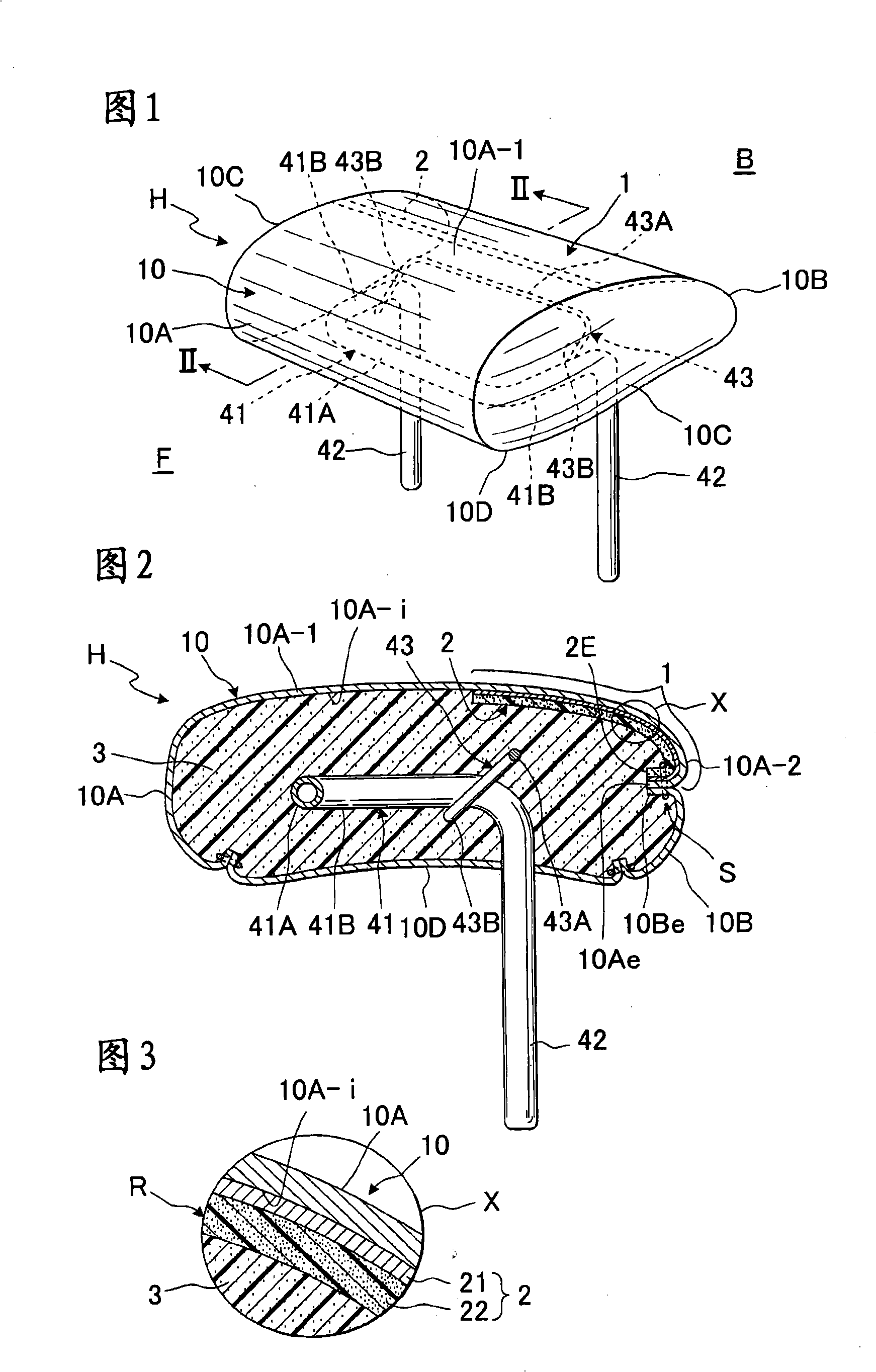
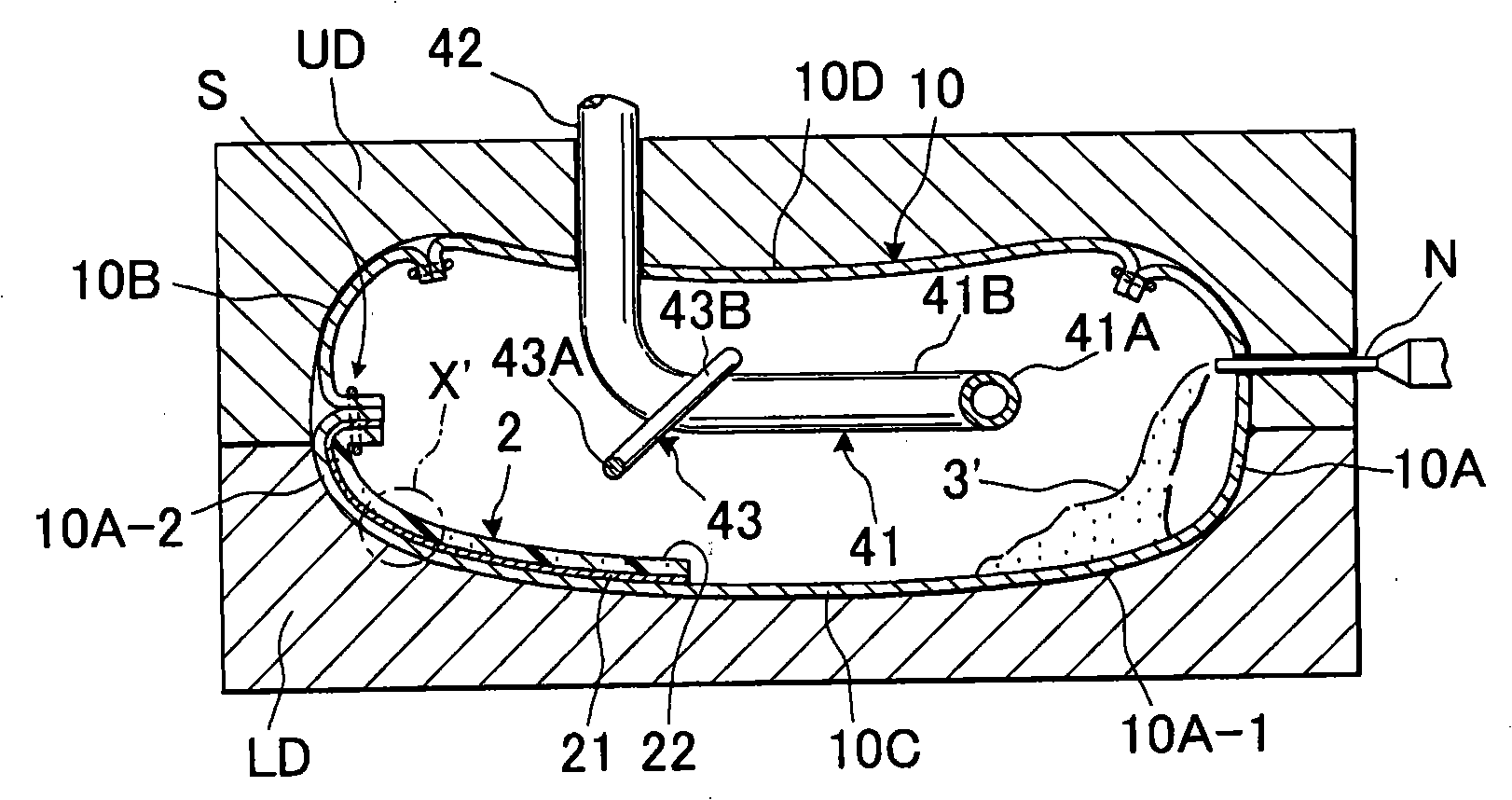
[0026] Referring to Figures 1-6, a schematic preferred form of a headrest, generally designated H, in accordance with the present invention is shown.

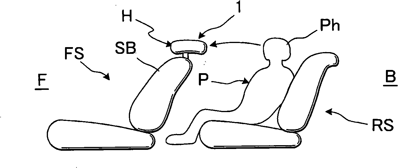
[0027] The head restraint H is essentially a head restraint type head restraint adapted to be mounted on a front seat, having a head receiving area for receiving the head of a passenger seated in the rear seat in an emergency such as a collision and absorbing the head restraint impact. That is, from Figure 4 As can be seen in , the head restraint H is arranged on the seat back SB of the front seat FS and has a head receiving area 1 defined therein at a point, indicated by the arrow, which is in the event of a collision at a particular passenger's The point at which the head Ph of the rear seat passenger P on the rear seat RS hits by the forward inertia.

[0028] It should be noted that the terms "forward" or "forwardly" refer to Figure 4 The seat structure in the cab of the vehicle shown and the front side F of the headrest ...


PUM


Abstract

A head protection head pillow comprises a decoration covering component; the decoration covering component is provided with a head receiving area used for being impacted by the head of a back seat passenger under an impact situation as well as an impact suction framework arranged in the decoration covering component. Reinforcing pieces are arranged on the points corresponding to the head receiving area on the inner surface of the decoration covering component, thus preventing the decoration covering component from cracking under the situation that the head of the back seat passenger impacts the head receiving area.

Description

technical field [0001] The present invention relates to a headrest for an automatic seat, in particular to a headrest of the type having an impact provided at the point where the head of a passenger sitting in the rear seat strikes in the event of a collision Absorb frame. Background technique [0002] When, for example, a collision occurs, a huge impact load is applied to the vehicle body, causing the vehicle to stop suddenly, which in turn causes the head of the seated passenger on the rear seat to strongly hit the front seat under the action of the forward inertia of the seated passenger. headrest. [0003] For such a strong head impact to a rear seat passenger, it often happens that the covering material of the front seat headrest with which the passenger's head strikes is partially broken or peeled off. [0004] A head restraint of the head protection type is known which has a shock absorbing frame provided therein, the shock absorbing frame being used for the front s...

Claims


Application Information

Patent Timeline
IPC IPC(8): B60N2/48
Inventor 糟谷隆
Owner TACHI S CO LTD
Why Eureka
Try Eureka