U-shaped anchorage cable

A U-shaped, anchor cable technology, which is applied in the direction of installation of anchor rods, sheet pile walls, building components, etc., can solve the problems of inconvenient replacement of anchor cables and inability to guarantee long-term anchorage, so as to achieve dispersed concentrated stress and anchor cable anchorage Reliable, wide-ranging effects

Active Publication Date: 2008-12-31
LIUZHOU OVM MASCH CO LTD
View PDF4 Cites 10 Cited by
  • Summary
  • Abstract
  • Description
  • Claims
  • Application Information

AI Technical Summary

Problems solved by technology

[0003] The technical problem to be solved by the present invention is to provide a U-shaped anchor cable that is beneficial to disperse the concentrated stress of the reinforced structure, improve the bearing capacity of the structure, and can reliably ensure the prestressing of the anchor cable. At the same time, the U-shaped anchor cable also It can solve the problems that the existing anchor cables are inconvenient to replace, the long-term anchorage cannot be guaranteed, and there are important hidden dangers in project operation

Method used


Image

  • U-shaped anchorage cable
  • U-shaped anchorage cable
  • U-shaped anchorage cable

Examples


Embodiment 1

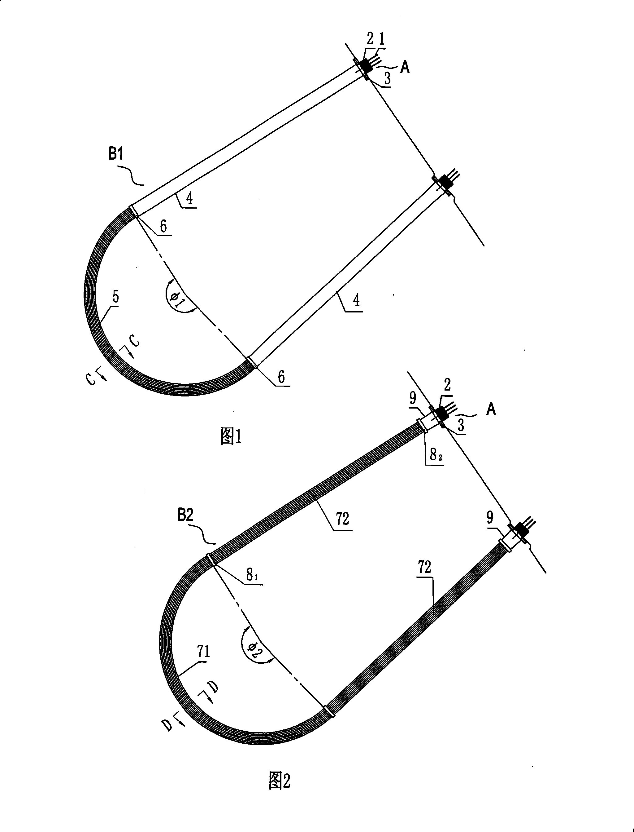
[0028] A U-shaped anchor cable whose U-shaped pipe seat is arc-shaped, as shown in Figure 1, the anchor cable includes an anchor cable body B1 and an outer anchor head A composed of an anchor 2 and an anchor pad 3. There are two outer anchor heads, and there is a long steel pipe 4 under the anchor backing plate 3 of the two outer anchor heads respectively, and the U-shaped pipe seat that the anchor cable body B1 passes through is an arc-shaped pipe composed only of arc-shaped segments. The wire splitting pipe seat 5, the central angle φ1 of the arc section is 190°, the two ends of the arc section are equipped with connecting plates 6 perpendicular to the axis of the pipe seat, and the lower ends of the two long steel pipes 4 are connected with the arc-shaped wire splitting pipe seat respectively. The connecting plates 6 at the two ends of the 5 are welded or flanged, and the anchor cable steel strands of each single cable body connected to the two outer anchor heads pass throug...

Embodiment 2

[0031] A U-shaped anchor cable whose straight section of the U-shaped pipe seat is extended to the orifice. As shown in Figure 2, the anchor cable includes an anchor cable body B2 and an outer anchor head A composed of an anchor 2 and an anchor plate 3. There are two outer anchor heads, and there is a section of short steel pipe 9 under the anchor backing plate 3 of the two outer anchor heads respectively. The lengthened U-shaped wire-separating pipe seat composed of straight section 72, the central angle φ2 of the arc section is 190°, the length of the straight section is 30000mm, and the connecting plate 8 perpendicular to the axis of the pipe seat is installed on the straight section 72 at both ends of the U-shaped pipe seat 1 ,8 2 , there is a short steel pipe 9 under the anchor backing plates of the two outer anchor heads respectively, and the arc section 71 and the straight section 72 of the U-shaped pipe seat pass through the connecting plate 8 1 Connection, the straig...


PUM


Abstract

Disclosed is a U-shaped anchor cable which comprises an anchor cable body and an outer anchor head composed of an anchoring device and an anchor plate; the anchor cable has two outer anchor heads; a U-shaped tube holder is threaded through the middle segment of the integrally-connected anchor cable body; the U-shaped tube holder is composed of an arc segment and a linear segment; the central angle of the arc segment of the U-shaped tube holder is from 45 degrees to 270 degrees; the length of the linear segment is from 0 to 50000mm; connecting plates vertical to the axial line of the tube holder are arranged on both ends of the U-shaped tube holder; steel pipes are respectively arranged under the anchor plates of the two outer anchor heads; the connecting plates on both ends of the U-shaped tube holder are respectively welded with the steel pipes or connected with the flanges; an anchor cable steel strand is threaded through the steel pipes and the U-shaped tube holder with both ends anchored on the outer anchor heads; the U-shaped tube holder is a U-shaped tube with a large diameter or with a plurality of U-shaped divided guide tubes inside, or can be constructed by a plurality of U-shaped divided guide tubes. The U-shaped anchor cable facilitates the dispersion of the centralized stress of the fixed structure and improves the bearing capacity of the structure.

Description

Technical field: [0001] The invention relates to a prestressed tendon anchor device, in particular to an anchor cable which is beneficial to disperse the concentrated stress of the reinforced structure and improve the bearing capacity of the structure. Background technique: [0002] In the original geotechnical anchor cable system, each bundle of anchor cables is a relatively independent anchor cable system, such as Image 6 As shown, the transmission of the prestress is independent of each other. The realization of the anchoring force has a great relationship with the construction quality and the geological body, which is not easy to guarantee. Moreover, once the anchor cable is installed, it will not be replaced and is a permanent concealed item, such as the anchor cable Deterioration of working conditions will cause heavy losses to the project. For the anchor cables with bonded tendons in some other bridges or buildings, there is also the problem that the anchor cables ca...

Claims


Application Information

Patent Timeline
Patent Type & Authority Applications(China)
IPC IPC(8): E02D5/74E21D21/00E04C5/12E04C5/08E01D19/14
Inventor 甘国荣谭柳芳
Owner LIUZHOU OVM MASCH CO LTD
Why Eureka
Try Eureka