
Driving-force transmission mechanism and image forming apparatus equipped therewith

A technology of power transmission device and pressure, applied in the direction of friction transmission device, transmission device, transmission device parts, etc., can solve the problems of increased product cost, complicated assembly operation and high material cost

Inactive Publication Date: 2008-12-31
KYOCERA DOCUMENT SOLUTIONS INC
View PDF1 Cites 5 Cited by
  • Summary
  • Abstract
  • Description
  • Claims
  • Application Information

AI Technical Summary

Problems solved by technology

[0005] However, in the device of Patent Document 1, since two track rings made of expensive tool steel and other materials must be used, the material cost is high, which directly leads to an increase in product cost.
In addition, if the number of parts that require high-precision assembly such as the raceway ring increases, the assembly work becomes complicated and the manufacturing cost increases.

Method used


Image

  • Driving-force transmission mechanism and image forming apparatus equipped therewith
  • Driving-force transmission mechanism and image forming apparatus equipped therewith
  • Driving-force transmission mechanism and image forming apparatus equipped therewith

Examples


Embodiment approach

[0068] The second modified embodiment shown below is a preferred mode in which the outer ring 10 presses the planetary rollers 22 .

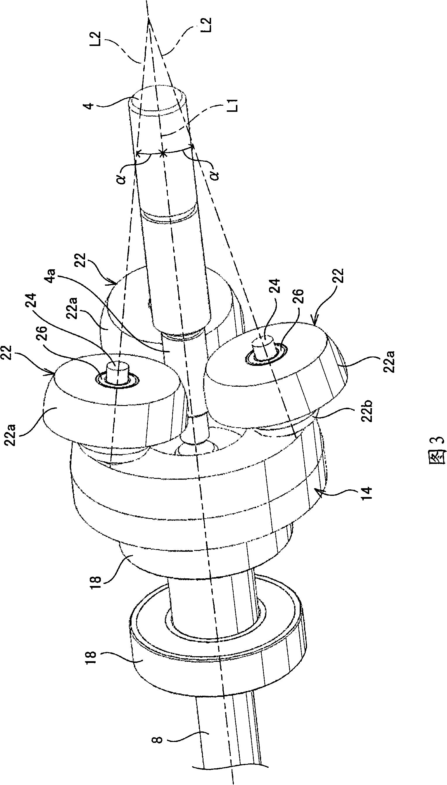
[0069] Figure 11 It is an enlarged view showing a portion where the planetary rollers 22 are pressed by the outer ring 10 . As described above, by pressing the pressing surface 10b of the outer ring 10 against the pressure receiving surface 22b of the planetary roller 22 with a large force, the planetary roller 22 is slightly moved along the shaft member 24 (peripheral axis L2). At this time, the planetary rollers 22 press the sun roller 4 with a large force in the radial direction according to the inclination of the peripheral axis L2 with respect to the rotational axis L1 of the sun roller 4 . In the presence of grease, a frictional force is generated between the peripheral surface 22a of the planetary roller 22 and the peripheral surface 4a of the sun roller 4 by this pressing force.

[0070] At this time, if Figure 11 As indicated by ar...


PUM


Abstract

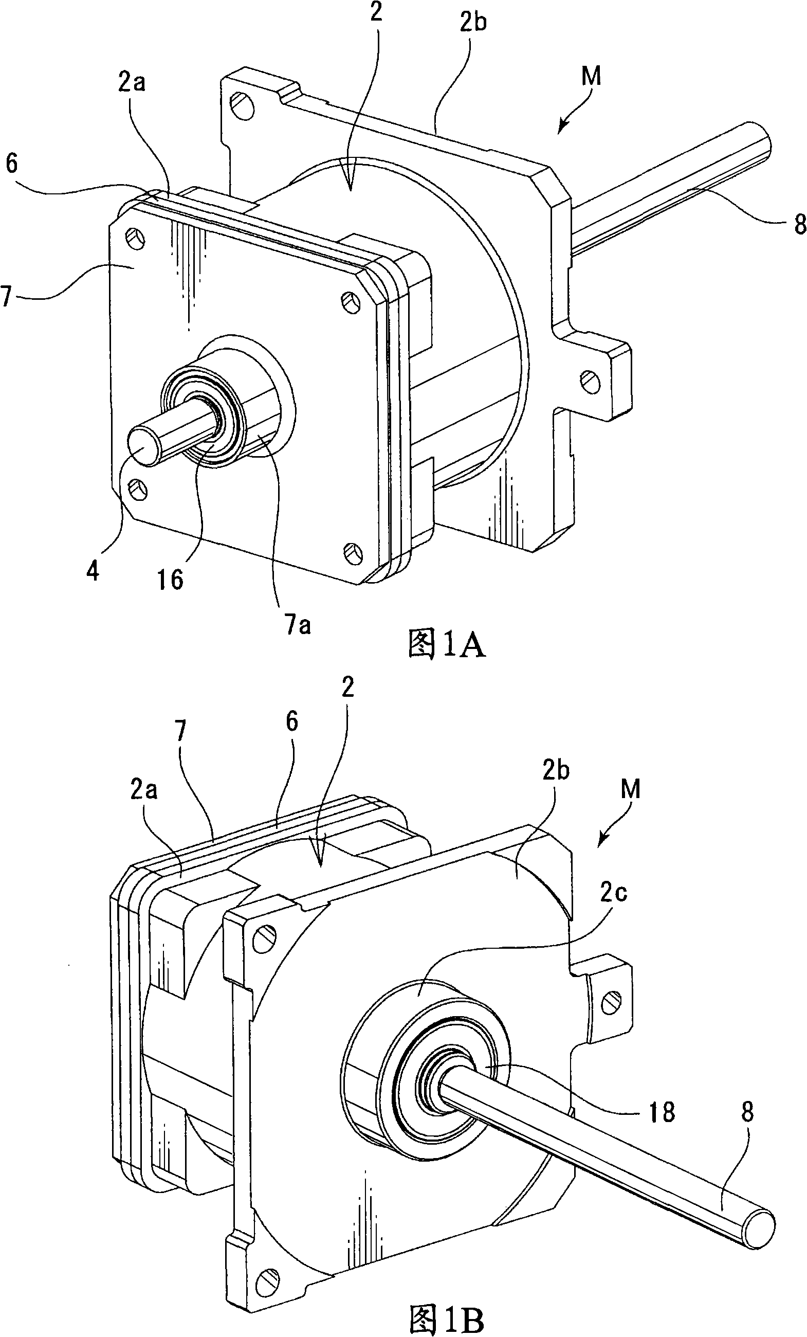
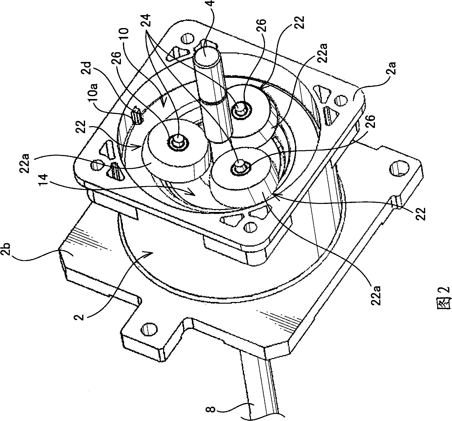
The invention provides a traction-drive force transmission mechanism and a image forming device equipped with the same. The traction-drive force transmission mechanism, includes a sun roller rotatable about a first axis and a plurality of shafts. Each is disposed on an adjacent axis inclined relative to the first axis. Planetary rollers are disposed along an outer peripheral surface of the sun roller and are supported respectively by the shaft. A carrier holds each of the shafts in the inclined posture and is adapted to be rotated about the first axis together with the planetary rollers. A pressing member pressingly moves each planetary roller in a direction for reducing a distance to the first axis so as to press each planetary roller against the outer peripheral surface of the sun roller. Thus a driving force can be transmitted to a traction force between the sun roller and each of the planetary rollers.

Description

technical field [0001] The present invention relates to a frictional power transmission device which can perform power transmission or reduce the rotational speed by utilizing the frictional force generated between rollers, and an image forming apparatus equipped with the same. Background technique [0002] As the prior art related to the frictional power transmission device, the known structure is to arrange a plurality of planetary rollers around the sun roller connected to the rotating shaft, and support the planetary shafts of each planetary rollers with brackets (for example, Japanese Patent Laid-Open Publication 2000 -329206, hereinafter referred to as "Patent Document 1"). In the device of Patent Document 1, the planetary rollers are rotated by the friction generated between the sun rollers and the planetary rollers, and the circumferential motion of the planetary rollers orbiting around the outer side of the sun rollers is transmitted to the output shaft by the suppo...

Claims


Application Information

Patent Timeline
Patent Type & Authority Applications(China)
IPC IPC(8): F16H13/08F16H57/04F16H57/12G03G15/00
Inventor 丸本武志
Owner KYOCERA DOCUMENT SOLUTIONS INC
Learn More