
Distributed type intermittent thermal production control system

A control system, distributed technology, applied in heating system, hot water central heating system, space heating and ventilation, etc., can solve the problem of high return water temperature, unfavorable heat user's pressure head, difficult to balance and meet Heat users have different heat needs and other issues, achieving significant environmental benefits, reducing energy consumption in transmission and distribution, and eliminating or reducing the pressure head of excess resources

Inactive Publication Date: 2008-12-31
DALIAN MARITIME UNIVERSITY
View PDF0 Cites 9 Cited by
  • Summary
  • Abstract
  • Description
  • Claims
  • Application Information

AI Technical Summary

Problems solved by technology

[0002] The existing heat supply technology is based on the centralized circulation pump of the heat exchange station, which acts as the heat source pump, heat network pump and heat user pump to complete the entire transmission and distribution process of the heat medium. It is bound to be difficult to take into account and satisfy the entire Different heat demands of many heat users in different time and space in the heat network
Large flow and small temperature difference (about 10 degrees) are formed, and the return water temperature is high; relying on the high lift provided by the circulating pump at the outlet of the heat source to meet the resource pressure head at the most unfavorable heat user, often resulting in hydraulic and thermal imbalance , forming near heat and far cold; the system provides full-time heating, which causes huge waste due to the inability to adjust time-sharing and partitions on demand

Method used


Image

  • Distributed type intermittent thermal production control system
  • Distributed type intermittent thermal production control system

Examples


Embodiment Construction

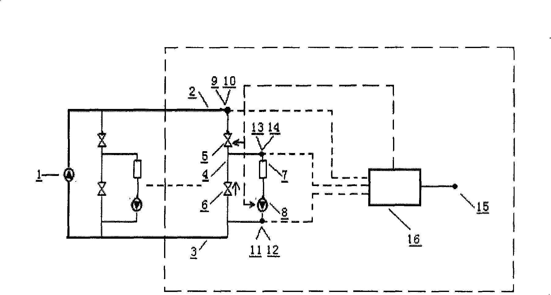
[0016] This system includes: the main network water supply pipe 2 and the return water pipe 3 connected to the heat source, the bypass pipe 4 connected to the branch water supply and return pipes of the building, and the electric switch valve 5 on the branch water supply pipe, that is, the main pipeline of the building. Manual valve on the bypass pipe 6, heat user building 7, variable frequency heat user pump 8, supply water temperature and pressure sensors 9, 10, return water temperature and pressure sensors 11, 12, mixed water temperature and pressure sensors 13, 14 , ambient temperature sensor 15 and intelligent controller 16.

[0017] The system works as follows:

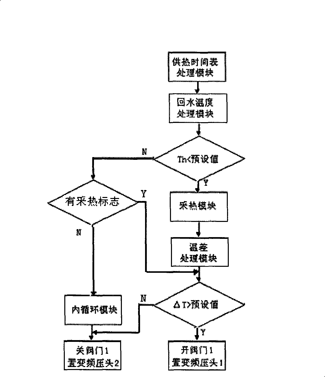
[0018] During the rough debugging of the system, according to the actual situation of the heat users (ground heat, cooling fins, etc.), the water mixing ratio required by the manual valve 6 does not need to be changed after the manual valve 6 is adjusted. During normal heat supply, the intelligent controller 16...


PUM


Abstract

The invention relates to a distributed-type intermittent heating controlling system, which belongs to the field of the building heat supplying system controlling technology. The heating controlling system aims to solve the energy wasting problems universally existing in the heat supplying operation in the northern cities that the Working Pressure Head is Redundant, the Temperature Difference is Small and the Flow is Large and the prior situation that the energy conservation force application point with enforcing actions is lack in the mixing network with different heat requirements. The purpose that the heat source intermittent heating and the continuous cycling heat supplying to the heat user according to the requirements are combined is realized through the distributed-type transportation and distribution controlling design, thereby the temperature difference of the supply and return water is enlarged, the flow of the systematic pipe network is reduced, the redundant working pressure head is decreased or eliminated, the different heat requirements of the heat user group at the different time interval is satisfied, and paving the way for adopting the measurement method according to the individual household. The enormous energy-saving space under the prior operation condition is converted into the distinct energy-saving reality through supplying the concrete force application point. The distributed-type intermittent heating controlling system has the advantages that the energy conservation effect is obvious, the heat supplying security is good, the adjustability is strong, and the heat controlling system is suitable for the new-building system and the reconstruction of the old system.

Description

technical field [0001] The invention belongs to the technical field of building heating system control. It is aimed at the ubiquitous energy waste problems such as "excessive capital and utilization pressure head, small temperature difference and large flow" in the heating operation of northern cities, and the current situation of lack of implementation behavior and energy-saving force points for mixed networks with different heat demands. Through the distributed transmission and distribution control design, the combination of intermittent heat collection from heat sources and on-demand continuous cycle heat supply to heat users is realized, thereby increasing the temperature difference between supply and return water, reducing the flow of system pipe networks, and reducing or eliminating the pressure of excess capital. Head, to meet the different thermal needs of different time periods of thermal user groups, and provide a foundation for household metering. By providing spec...

Claims


Application Information

Patent Timeline
IPC IPC(8): F24D19/10F24D3/00
Inventor 汪思源邢欣荣王道涵商静辉刘建伟赵永生
Owner DALIAN MARITIME UNIVERSITY
Learn More