Head-up-display system

A head-up display system and image technology, applied in optics, measuring devices, instruments, etc., can solve the problems of high cost of holographic components, blurred and complex virtual images, and achieve the effect of improving the depth of field viewing angle

Inactive Publication Date: 2008-12-31
OPUS MICROSYSTEMS CORP
View PDF0 Cites 33 Cited by
  • Summary
  • Abstract
  • Description
  • Claims
  • Application Information

AI Technical Summary

Problems solved by technology

[0003] In the prior art, the head-up display (HUD) uses a holographic element to generate a virtual image, but the holographic element needs to be embedded in the windshield of the car, so this method is more complicated, and the cost of the holographic element is higher
In addition, th

Method used


Image

  • Head-up-display system
  • Head-up-display system
  • Head-up-display system

Examples


Embodiment Construction

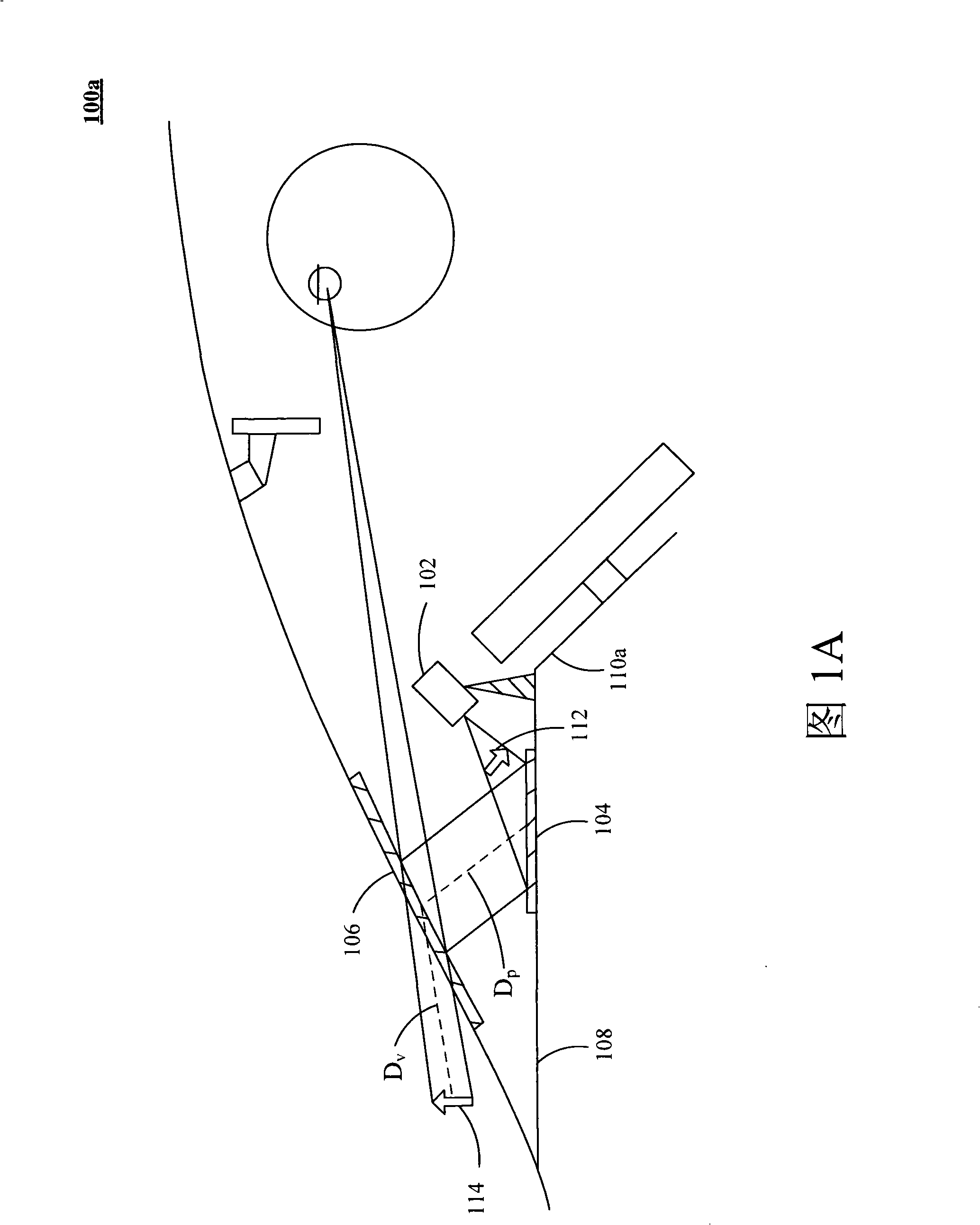
[0015] FIG. 1A is a schematic diagram of a head-up display system according to a first embodiment of the present invention. The head-up display system 100 a mainly includes an image generating device 102 , a diffusion unit 104 and an imaging unit 106 . The image generating device 102 is installed above the dashboard 110 a of the vehicle 108 . The image generating device 102 emits visible light to generate a solid image 112 . The diffusing unit 104 is coupled to the image generating device 102 to receive the visible light from the image generating device 102 to form the solid image 112 in the diffusing unit 104 . The diffusion unit 104 of the present invention is, for example, a diffusion film with a gain function to set the visible light within a specific viewing angle and to control the imaging brightness of the solid image 112 . The imaging unit 106 is coupled to the diffusion unit 104 to receive the visible light from the diffusion unit 104. By controlling the visible lig...


PUM

PropertyMeasurementUnit
Wavelengthaaaaaaaaaa

Abstract

The invention provides a head-up display system, comprising an image generation device, a diffusion unit and an imaging unit. The image generation device projects image information in the form of visible light. The visible light radiates the diffusion unit and forms a solid image; the imaging unit reflects the solid image coming from the diffusion unit to the eyes of a driver, thus forming a virtual image corresponding to the solid image; wherein, the length from the solid image to the imaging unit is equal to the length from the virtual image to the imaging unit. The head-up display system of the invention can also project the visible light to the imaging unit and reflect the visible light to the diffusion unit; subsequently, the visible light can be reflected to be imaging unit from the diffusion unit so as to form the virtual image.

Description

technical field [0001] The present invention relates to a display device, in particular to a head-up display system. Background technique [0002] A head-up display (HUD) device has been used in aircraft, especially for military flight piloting, for many years. In recent years, more and more civilian vehicles can also find its application. In order to reduce costs and integrate into the cockpit or instrument panel with limited space, the head-up display must further simplify components and mechanisms to reduce the volume of the entire system. Based on this concept, the laser light source that does not require a focusing lens group has been used in the head-up display system. The head-up display system receives the signal sent by the car, and converts the signal into a control signal of the laser light source, and then projects the laser to form an image for the driver to watch. Basically, if the laser light source is always on, the entire image frame is a spot of light. ...

Claims


Application Information

Patent Timeline
IPC IPC(8): G02B27/01G01C23/00
Inventor 洪昌黎林大为叶逢春
Owner OPUS MICROSYSTEMS CORP
Why Eureka
Try Eureka