Shock absorption positioning control method and device

A positioning control and acceleration technology, applied in mechanical oscillation control, non-electric variable control, control/adjustment systems, etc., can solve problems such as large stress and inability to set arbitrarily, reduce residual vibration and reduce adjustment workload Effect

Active Publication Date: 2008-12-31
IHI CORP
View PDF5 Cites 12 Cited by
  • Summary
  • Abstract
  • Description
  • Claims
  • Application Information

AI Technical Summary

Problems solved by technology

[0025] The above-mentioned conventional methods have problems such as (1) vibrations continue until they are canceled out, and (2) vibrations larger than the static vibrations due to acceleration are generated, s

Method used


Image

  • Shock absorption positioning control method and device
  • Shock absorption positioning control method and device
  • Shock absorption positioning control method and device

Examples


Embodiment 2

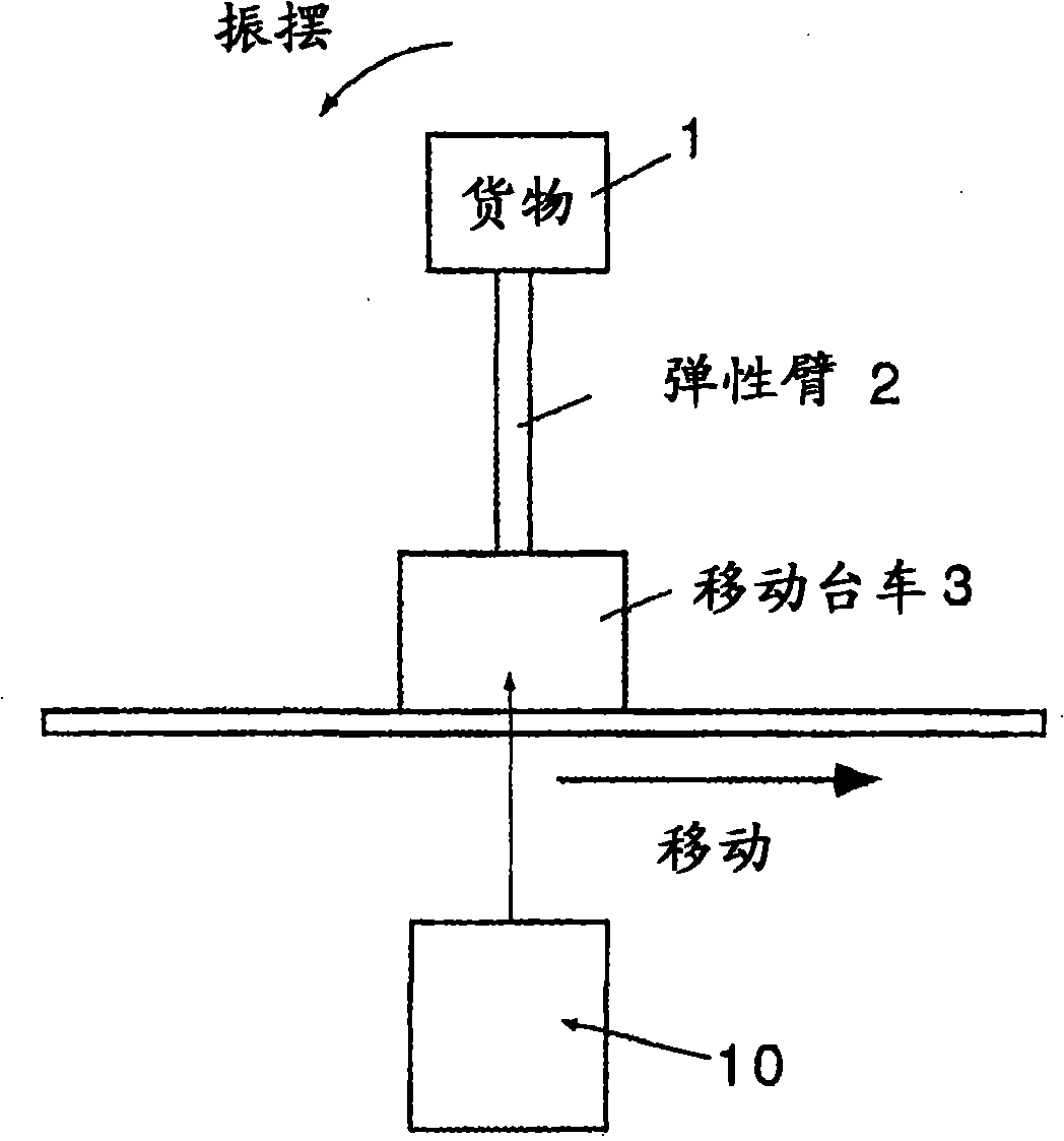
[0170] Such as Figure 14 As shown, in this example, a strain gauge 4 (such as a strain gauge) is provided on the base of the elastic arm 2, an accelerometer 5, 6 is provided on the cargo 1 and the mobile trolley 3, and external devices are provided to measure the cargo 1 and the movement. The laser rangefinders 7 and 8 for the position of the trolley 3 input their deformation, acceleration and position to the control device 10 .

[0171] With this structure, the actual runout can be measured from the respective deformation, acceleration and position.

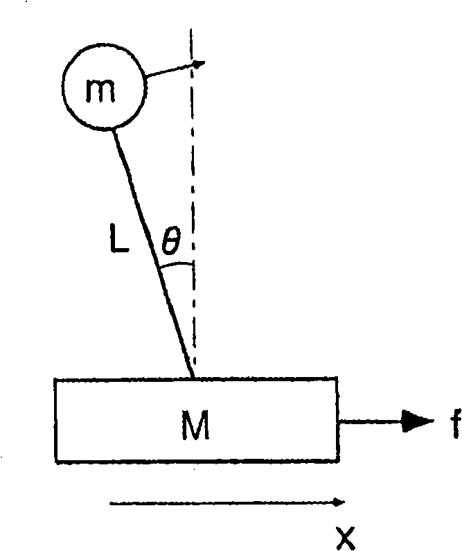
[0172] abovementioned Figure 2B can be used directly as Figure 14 model diagram. If modeled as Figure 2B For the spring-mass system shown, the natural period T is shown in formula (15) in Mathematical Formula 4, but for example, p and q can be set as parameters for correcting modeling errors, as shown in formula (16).

[0173] [mathematical formula 4]

[0174] T = 2 π ...


PUM


Abstract

A vibration reduction position control method and a device which can restraint the vibration of a moving object which generates vibration and elastic deformation and can determine the position are provided. The vibration of the moving object is modeling by single-degree-of-freedom spring-particle system, and the natural period T of the model is determined, the acceleration curves of speedup and speed reduction are defined as the trapezium curves for speed up and speed reduction including constant jerky, and each constant jerky time is set to be integer times of the natural period.

Description

technical field [0001] The present invention relates to a vibration-damping positioning control method and device for suppressing the vibration of a mobile body that produces vibration and elastic deformation during acceleration and deceleration, and accurately determining the position. Background technique [0002] Mobile objects such as cranes and manipulators, which have a structure that tends to vibrate and elastically deform during acceleration and deceleration, vibrate back and forth and elastically deform during movement, making it difficult to determine the correct position. Therefore, as a means of suppressing the vibration and specifying the position by performing control in an open-loop manner without measuring such vibration of a moving body in real time, various means of setting a velocity profile consistent with the natural period have been proposed so far (for example, Non-Patent Document 1. Patent Documents 1 to 6). [0003] Non-Patent Document 1 first propo...

Claims


Application Information

Patent Timeline
IPC IPC(8): G05D19/00
Inventor 铃木俊太郎袖子田志保
Owner IHI CORP
Why Eureka
Try Eureka