Composite switch control system

A composite switch and control system technology, which is applied in the direction of electric switches, electrical components, circuits, etc., can solve the problems of increased hardware costs, troublesome overall circuit layout of notebook computers, etc.

Inactive Publication Date: 2008-12-31
QUANTA COMPUTER INC
View PDF0 Cites 2 Cited by
  • Summary
  • Abstract
  • Description
  • Claims
  • Application Information

AI Technical Summary

Problems solved by technology

In this way, when the number of buttons increases, the hardware cost will increase accordingly
In addition, the number of wirings associated with the above design will also be too much, which will cause troubles in the overall circuit layout of the notebook computer.

Method used


Image

  • Composite switch control system
  • Composite switch control system

Examples


Embodiment Construction

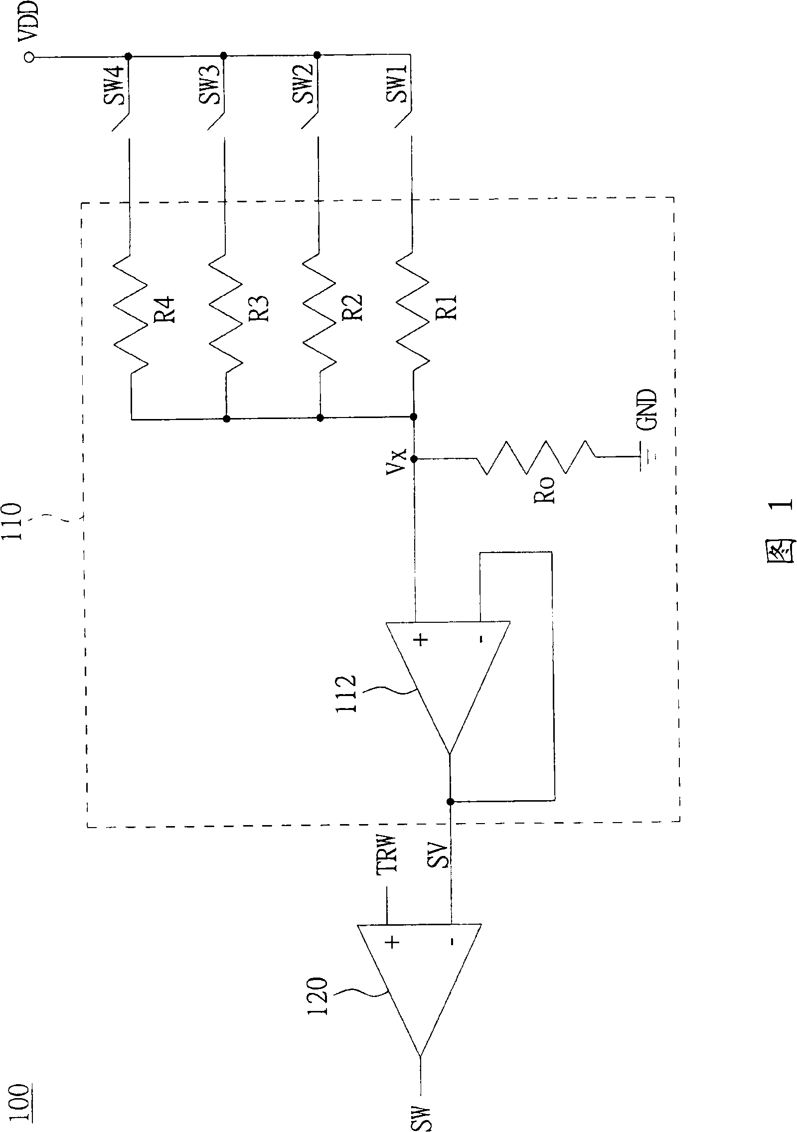
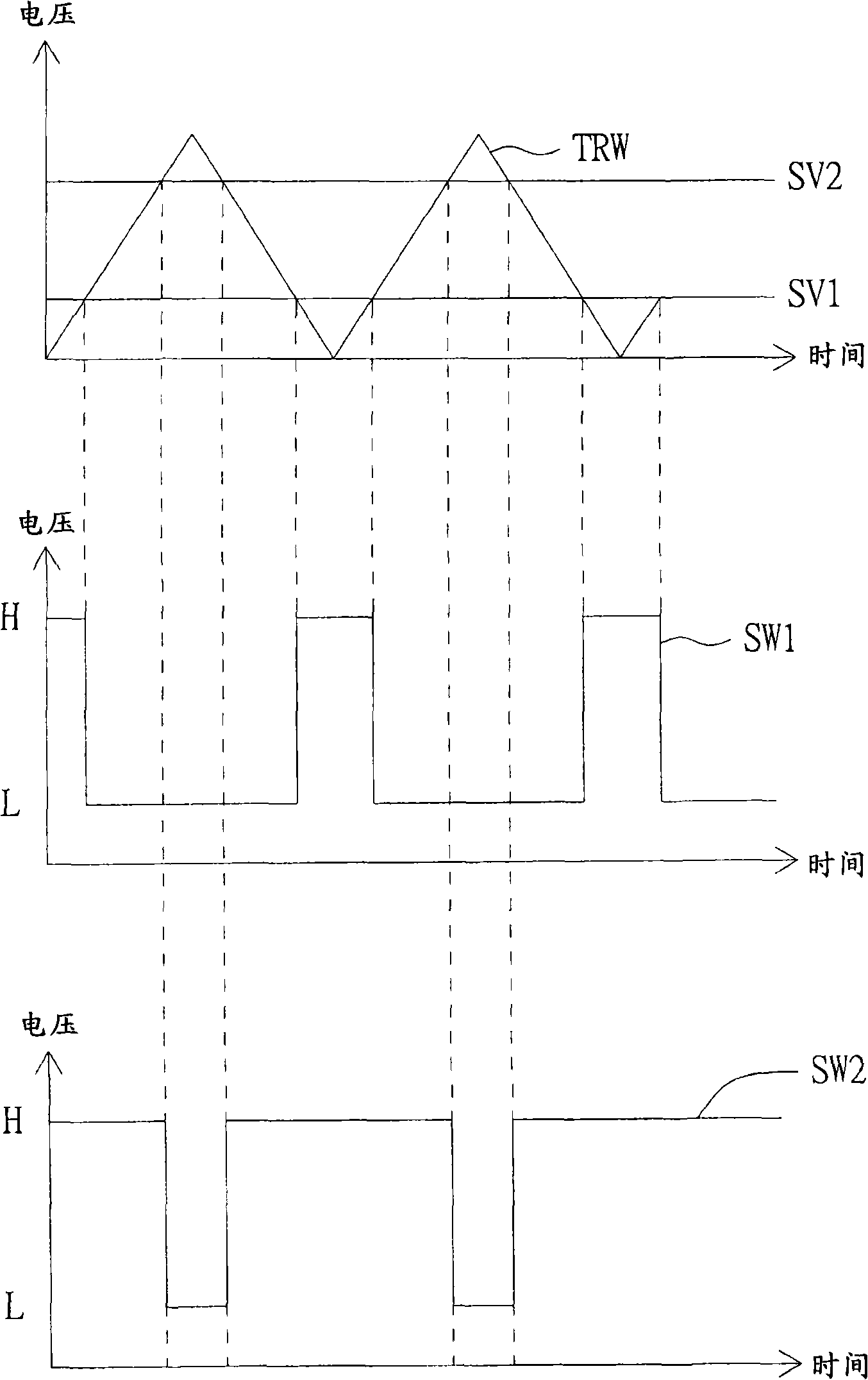
[0013] The present invention proposes a compound switch control system, which uses a simple circuit to change the duty cycle of the switch state signal, so that the keyboard controller can judge the states of multiple switches through a single universal input / output.

[0014] Please refer to FIG. 1 , which shows a schematic diagram of a composite switch control system according to a preferred embodiment of the present invention. The composite switch control system 100 includes a plurality of switches SW1 - SW4 , a switching voltage control circuit 110 and a comparator 120 . The first terminals of the switches SW1-SW4 are all coupled to the working voltage VDD. The switching voltage control circuit 110 converts the working voltage VDD into the switching voltage SV according to the state of the switches SW1-SW4 (that is, whether the switches SW1-SW4 are open or not). The comparator 120 compares the switch voltage SV and the reference voltage TRW to output a switch state signal ...


PUM


Abstract

The invention discloses a combined type switch controlling system which comprises a plurality of switches, a switching voltage control circuit and a comparator. The switching voltage control circuit transforms operating voltage to switching voltage according to the statuses of the switches. The comparator compares the switching voltage with reference voltage so as to output a switch status signal to a keyboard controller, wherein, the operation cycle of the switch status signal corresponds to the statuses of the switches.

Description

technical field [0001] The invention relates to a composite switch control system, and in particular to a composite switch control system which saves general purpose I / O pins. Background technique [0002] With the rapid development of notebook computer technology, there are more and more additional functions, and the number of buttons (buttons) corresponding to each function on the notebook computer also increases thereupon. Most of the buttons on the current notebook computer are processed by using a switch (switch) coupled to a general purpose I / O (General Purpose I / O) pin on the keyboard controller. That is, each button needs to correspond to a general-purpose input / output pin. For example, 8 buttons require 8 general purpose I / O pins. In this way, when the number of buttons increases, the hardware cost will increase accordingly. In addition, the number of wirings associated with the above design will also be too much, which will cause troubles in the overall circuit ...

Claims


Application Information

Patent Timeline
Patent Type & Authority Applications(China)
IPC IPC(8): H01H9/54H01H13/70
Inventor 卢政成吴育苍
Owner QUANTA COMPUTER INC
Why Eureka
Try Eureka