Multi-point triggering fixed point tracking monitoring method and system

A monitoring system and key monitoring technology, applied in the direction of closed-circuit television systems, instruments, anti-theft alarms, etc., can solve problems such as insufficient prominence, and achieve the effects of rapid response, improved monitoring efficiency, and high degree of automation

Inactive Publication Date: 2008-12-31
SOUTH CHINA UNIV OF TECH
View PDF4 Cites 41 Cited by
  • Summary
  • Abstract
  • Description
  • Claims
  • Application Information

AI Technical Summary

Problems solved by technology

[0005] The purpose of the present invention is to overcome the deficiency that the existing monitoring system generally does not focus on the prominence of the key monitoring objects, and to provide a monitoring method and monitoring system for multi-po

Method used


Image

  • Multi-point triggering fixed point tracking monitoring method and system
  • Multi-point triggering fixed point tracking monitoring method and system
  • Multi-point triggering fixed point tracking monitoring method and system

Examples


Embodiment Construction

[0027] The specific embodiments of the present invention will be further described below in conjunction with the accompanying drawings.

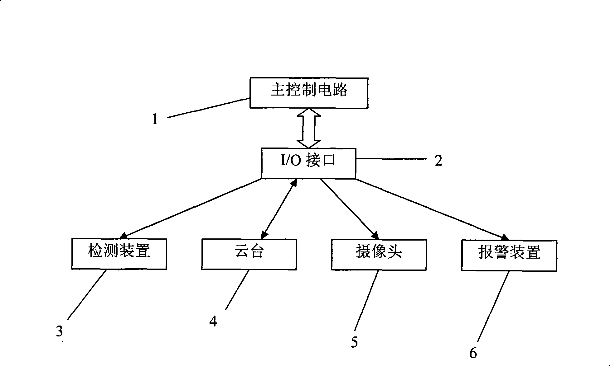
[0028] 1. Realize a camera 5 to automatically monitor multiple targets at a fixed point. This system uses a single-chip microcomputer as a control chip. When there is no situation, that is, in free mode, the camera 5 scans each target in turn according to a certain order, and so on. Until a certain The occurrence status of a monitoring target. When something happens to the target, such as when someone invades the defense area and triggers the sensor, the infrared emitter on the target will send a signal to the main control circuit, and the main control circuit determines the horizontal and vertical rotation of the gimbal 4 motor through the control algorithm in the memory. Then control the driving circuit of the horizontal and vertical motors to turn the pan-tilt 4 to the target orientation; and send a photographing instruction to the camera...


PUM


Abstract

The method sets a plurality of key monitoring positions in place to be monitored, when no abnormal target occurs in the key monitoring monitor positions, the monitoring system controls the rotation of a horizontal stage to make the cam scanning in turn each position in the place to be monitored; when a testing apparatus in the monitoring system detects an abnormity occurs in one position of the plurality of key monitoring positions, the monitoring system controls the horizontal stage to make the cam performing camera shooting scanning to the key position where abnormity occurs. The monitoring system includes a horizontal stage, a video camera, a testing apparatus and a main control circuit, wherein the main control circuit includes a horizontal stage control circuit a camera control circuit and a single chip; the testing apparatus transmits the testing result to the single-chip in the main control circuit, and then the single-chip controls the horizontal stage and the video camera. The invention has advantages of simple structure, high degree of automation, strong practicability and high efficiency.

Description

technical field [0001] The invention relates to the technical field of monitoring, in particular to a monitoring method and a monitoring system for multi-point triggering and fixed-point tracking. Background technique [0002] Existing security monitoring equipment can be roughly divided into three types: monitoring at fixed locations, with a small monitoring range and lack of flexibility; monitoring systems equipped with pan-tilts, where the camera can rotate left and right and up and down, and generally require online real-time operation by humans. The monitoring range is large, people are prone to fatigue and the continuous response speed is slow; through image processing technology, automatic tracking of moving objects is realized. Due to the requirement of online real-time processing of a large number of image files, the realization of the system is relatively expensive. [0003] Such as the Chinese utility model patent published on May 09, 2003, titled "Remote Control ...

Claims


Application Information

Patent Timeline
IPC IPC(8): H04N7/18G08B13/196
Inventor 谢巍张浪文郑晓平谢风林梁伟华杨文俭蔡熙吴汉龙
Owner SOUTH CHINA UNIV OF TECH
Why Eureka
Try Eureka