Supercharge Your Innovation With Domain-Expert AI Agents!

Blood pressure meter

A sphygmomanometer and blood pressure value technology, which is applied in the field of sphygmomanometers, can solve the problems that the display part is not facing forward, it is difficult to see the blood pressure value of the display part, and it is difficult to see the blood pressure value, etc., and the effect of easy compression operation is achieved.

Inactive Publication Date: 2009-01-07
CITIZEN WATCH CO LTD
View PDF3 Cites 2 Cited by
  • Summary
  • Abstract
  • Description
  • Claims
  • Application Information

AI Technical Summary

Problems solved by technology

[0009] However, as in the above-mentioned Patent Document 1 and Patent Document 2, when the grip part is arranged in the same phase as the display part, if the grip part is held in the direction of the recessed part of the palm, the display part will not face the operator, thereby becoming It is difficult to see the blood pressure value displayed on the display
In addition, in the above-mentioned Patent Document 3, since the grip part is arranged on the side of the display part, if the grip part is held in the direction of the recessed part of the palm, for the same reason, the display part will not face the operator and become difficult to see. to the blood pressure value displayed on the display
[0010] That is, in the above-mentioned Patent Documents 1 to 3, when the hand pump is gripped together with the grip part and the hand pump is compressed and operated, the blood pressure value displayed on the display part is easily displayed if the front of the display part faces the user. If you see it, your fingers will come into contact with the grip, and the compression operation of the hand pump will become difficult
On the other hand, if the compression operation of the hand pump is facilitated by keeping the fingers from touching the grip, the display unit does not face the operator, making it difficult to see the blood pressure value displayed on the display unit.

Method used


Image

  • Blood pressure meter
  • Blood pressure meter
  • Blood pressure meter

Examples


Embodiment Construction

[0035] Hereinafter, an example of an embodiment of the present invention will be described with reference to the drawings.

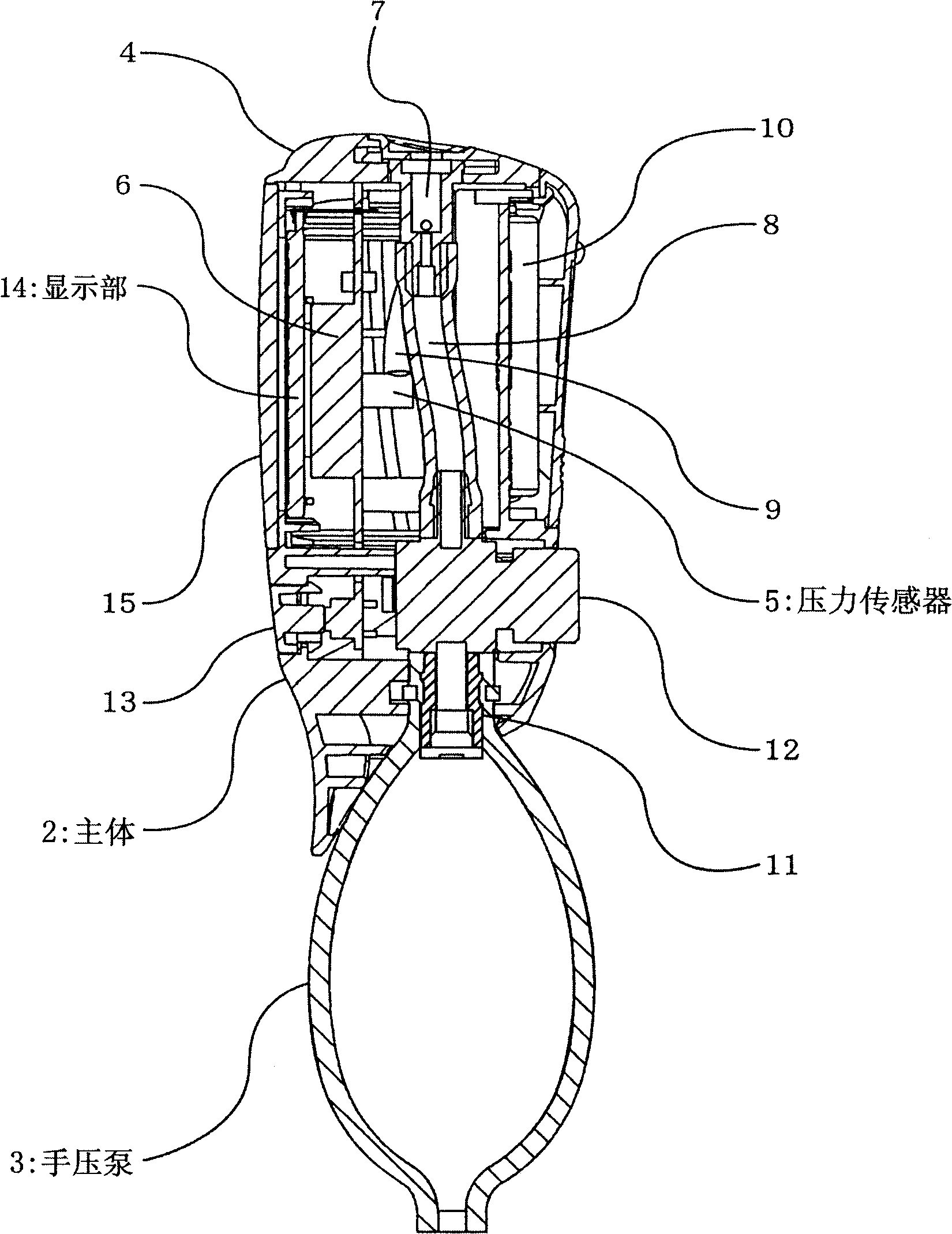
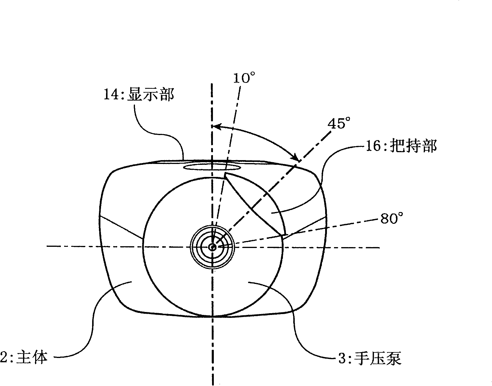
[0036] figure 1 It is a front view of a sphygmomanometer as an example of an embodiment of the present invention, figure 2 yes figure 1 The A-A line profile, image 3 and Figure 4 From figure 1 The figure observed in the direction of the arrow B, Figure 5 It is a diagram for explaining the positional relationship between the maximum diameter of the hand pump and the extension end of the grip part, Figure 6 It is a diagram for explaining the effect of increasing the compression stroke of the hand pump utilizing the gap between the hand pump and the grip.

[0037] A sphygmomanometer 1 as an example of an embodiment of the present invention includes a main body 2 and a hand pump 3, wherein the main body 2 is detachably attached to a cuff ( (not shown), the hand pump 3 is attached to the lower part of the main body 2, and is composed of a rubber...


PUM


Abstract

A blood pressure meter (1) including: a body (2) which is connected through a tube with a cuff and which has a display section (14) which displays a blood pressure value determined by a control section (6) based on a variation in a pressure measurement value by a pressure sensor (5) in the cuff; a spherical hand pump (3) which is attached to the body (2) and which supplies air by a compressing operation to the cuff to inflate the cuff; and a grasp section (16) which is extended from the body (2) along the outer surface of the pump (3) in the direction of the axis of the hand pump (3) and which is capable of being grasped with the pump (3), the display section (14) being placed at the body (2) so that a blood pressure value is visible from a direction substantially normal to the axis of the pump (3), the center line in the width direction of the grasp section (16) is placed at a position at 45 DEG about the axis line of the pump (3) relative to the display section(14).

Description

technical field [0001] The present invention relates to a sphygmomanometer in which a spherical hand pump for inflating a cuff is integrally provided on a main body provided with a display unit for displaying blood pressure values. Background technique [0002] As a sphygmomanometer, it is known to have a main body connected to a cuff detachably attached to the arm of the measurement subject through a tube, and to attach air to the main body and supply air into the cuff by a compression operation so that the Sphygmomanometer with bulbous hand pump with inflated cuff. [0003] The main body is equipped with a pressure sensor for measuring the pressure inside the cuff, and a control unit for determining the blood pressure value based on the fluctuation of the measured value. In addition, on the outer surface of the main body, a display unit such as a liquid crystal panel displaying the blood pressure value determined by the control unit is arranged, and the display unit is ar...

Claims


Application Information

Patent Timeline
Patent Type & Authority Applications(China)
IPC IPC(8): A61B5/022
CPCA61B5/02225A61B5/02141A61B2560/0406A61B5/022
Inventor 高桥一成铃木孝子
Owner CITIZEN WATCH CO LTD
Features
  • R&D
  • Intellectual Property
  • Life Sciences
  • Materials
  • Tech Scout
  • Unparalleled Data Quality
  • Higher Quality Content
  • 60% Fewer Hallucinations
Learn More